
What is Resistance? Electrical Resistance
Electrical resistance is one of the key attributes in an electrical circuit – it determines the current flowing for a given voltage.
Resistance Tutorial Includes:
What is resistance
Ohms Law
Ohmic & Non-Ohmic conductors
Resistance of filament lamp
Resistivity
Resistivity table for common materials
Resistance temperature coefficient
Voltage coefficient of resistance, VCR
Electrical conductivity
Series & parallel resistors
Parallel resistors table
There are three basic measurements which can be made in an electrical circuit. Voltage and current are the first two, and the third is resistance.
As electrical resistance is such a basic concept in electrical and electronic circuits it is necessary to answer some questions: what is resistance, what are resistors, and how resistance affects circuits.
What is resistance?
Before looking at what resistance is, it is necessary to understand a little about current and what it is. Essentially a flow of current in a material consists of a movement of electrons in one direction. In many materials there are free electrons moving about randomly within the structure. While these move randomly there is no current flow, because the number moving in one direction will be equal to the number moving in the other. Only when a potential causes a drift in a particular direction can a current be said to flow.
What is resistance
Resistance is the hindrance to the flow of electrons in material. While a potential difference across the conductor encourages the flow of electrons, resistance discourages it. The rate at which charge flows between two terminals is a combination of these two factors.
If two different conductors are placed in a circuit, then the amount of current found to flow in each may not be the same. There are a number of reasons for this:
- The first is that the ease with which electrons are able to move within the structure of the material. If the electrons are bound tightly to the crystal lattice, then it will not be easy to pull them free so that there can be a drift of electrons in a particular direction. In other materials there are very many free electrons drifting randomly around the lattice. It is these materials that allow a current to flow more easily.
- Another factor that affects the electrical resistance of an item is its length. The shorter the length of material, the lower its overall resistance.
- The third is the cross sectional area. The wider the cross sectional area the lower the resistance as there is more area through which the current can flow.
In most cases conductors are required to carry current with as little resistance as possible. As a result copper is widely used because current flows easily within its structure. Also its cross sectional area is made wide enough to carry the current without any undue resistance.
In some instances it is necessary to have elements which resist the flow of current. These items are called resistors and they are made out of materials which do not conduct electricity as well as materials like copper or other metals.
Resistance analogy
The concept of resistance is not always easy to understand because it is not possible to visibly see the quantities involved: voltage, current and resistance itself are all rather invisible quantities to the naked eye, although they can be detected and measured in a variety of ways.
One analogy that helps introduce the concept of resistance is that of a water tank with a pipe leading down from it. Whilst we don't want to take the analogy too far it does help to explain the basic concept.

In this analogy, the water pressure caused but he height of the water is analogous to the voltage, the flow of water is analogous to the current, and the restriction of the water flow caused by the pipe is analogous to the resistance.

It can be seen that if the pipe was narrowed, or a tap added, the water flow would be further restricted and less water would flow. This would be analogous to increasing the resistance in in an electrical circuit, and this would reduce the current flow.

In a simple circuit comprising of a battery or voltage source and a resistor, then assuming the connecting wires have no resistance, then the higher the resistance the less the current that will flow.
The tap in the analogy of the water system corresponds to changing he resistance of the resistor. When the tap is off, then this is equivalent to a switch stopping any current flow into e electrical circuit.
Relationship between resistance, voltage and current
It can be imagined from he analogy of the water tank system, that increasing he voltage in an electrical circuit will increase the level of current flowing.
Similarly decreasing the resistance will increase the level of current as well.
In fact there is a relationship between voltage, resistance and current. Knowing two of the variables, it is possible to calculate the third.
The relationship between resistance, voltage and current is known as Ohm's law and it is one of the fundamental relationships in electrical and electronic science.
Resistance notation
The basic unit of electrical resistance is the Ohm as already mentioned. This is often denoted by the Greek symbol Ω.
In addition to this the basic unit can be prefixed by multipliers. This is because the range of values for electrical resistance can span many decades and it is necessary to have an easy notation that does not rely on counting the numbers of zeros in a number as this would easily lead to mistakes.
| Multiplier | Meaning | Name |
|---|---|---|
| R | units | Ohms, Ω |
| k | thousands | kilohms, kΩ |
| M | millions | Megohms, MΩ |
Occasionally resistances less than an ohm are encountered, these are measured in milliohms (m ) thousandths of an ohm.
Normally when resistances are indicated on an electronic circuit diagram they are denoted as 10R for a ten ohm resistor, 10k for a ten thousand ohm resistor, and 10M for a ten MΩ resistor. The reason for this is that the Greek letter omega is not as easy to use as the prefixes R, k, and M.
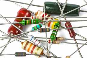
What are resistors?
In order that the current can be limited in a particular circuit, a component known as a resistor may be used. Resistors come in a variety of forms from large wired components, or even some using terminals to the very small surface mount components used in many electronics circuits today.
Resistors can be made from a variety of materials, carbon, metal oxide, metal film, resistance wire and the like. Resistors can come in different formats - different types of resistor have slightly different characteristics and this means that they may be used in different circuit applications.
Selecting the right type of resistor can help the circuit operate in the way it is intended. Although a resistor with a 10k resistance will have the same resistance whatever it is made from, characteristics like the temperature stability, noise, long term stability, spurious inductance and the like can be different for different types and this can affect the performance in some circuits.
Note on Resistors & Resistor Types:
Resistors are used in electrical and electronic circuits for a variety of purposes, but in each case they resist the current flow. There are many different types of resistor - their parameters mean that some types are more suitable for particular applications than others.
Read more about Resistors & Resistor Types
Resistance summary
When working with any electrical and electronics circuits, it is necessary to know what is resistance and how resistance affects the circuit. In view of the importance of resistance in circuits, resistors are widely used, possibly the most commonly used components in electronics circuits. These components are very easy to use, and the calculations associated with them are normally simple.
More Basic Electronics Concepts & Tutorials:
Voltage
Current
Power
Resistance
Capacitance
Inductance
Transformers
Decibel, dB
Kirchoff's Laws
Q, quality factor
RF noise
Waveforms
Return to Basic Electronics Concepts menu . . .


