
D-Type or D-Sub Connector
The D-Type or D-Sub (D-subminiature) connector has been in use since 1952 for many applications including for computer video and serial data links.
Connector Technology Includes:
Connector basics
Connector types
Specifications
Selecting the right connector
D-type connector
IEC power connector
Jack connector
XLR connector
IDC connector
PCB edge connector
DIN 41612 connector
The D-type or D-Sub range of connectors has been in widespread use for many years. They were first developed in 1952 by Cannon which is now part of ITT.
The D-type or D-Sub connector has been used in many applications as a multi-way connector, but it is probably most widely known as the connector used for RS-232 serial links.
In fact the D-type connector was used for the serial link on most computers for many years, and today variations of D-type connectors are still found on most computers.
The D-Sub was also used for many computer video links connecting computers to monitors, projects and other video displays.
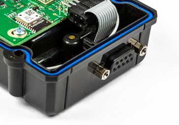
Note the fixing that themselves have an internal thread so that the connector mating half can be secured to prevent accidental disconnection.
The D-type connector was originally termed a sub-miniature connector, and as a result they were referred to as the D sub-miniature connectors, or D-sub for short.
Although these connectors were small when they were first introduced, the can no longer be thought of as true sub-miniature connectors.
These days, the connectors are very popular and are still incorporated into many new electronic circuit designs. Additionally a wide variety of these connectors is available from virtually all electronic component distributors.
D-type connector basics
D-sub connectors, i.e. D-type connectors most commonly consist or two and sometimes more parallel rows of connections.
The connectors have a D-format metal shell which gives this series of connectors its name. The D shape also prevents the connector from being inserted the wrong way round, thereby enabling easy connection, even when the connector may be obscured by some other item.
The D shape not only provides mechanical strength to the connector, but it also provides some limited screening as well - the metal shells of the plug and socket make contact to provide screening.
Also the panel mounting connectors are typically secured to the panel using nuts that have an additional thread that allows the mating connector to be secured to it to prevent it working loose.
The retention of the plug / socket combination in this way is particularly useful in applications where there may be some vibration, or the connections could work loose for some other reason.
Additionally the free connectors can have back-shells that can provide screening and can be connected to the cable screen, or if plastic, they can provide protection. Strain relief on the cable is also provided.
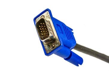
As would be expected, the connector containing the pins is the male D-type connector, whereas the connector containing the receptacle pins is the female.
The original D-type connectors had two rows on pins - the overall number of pins was an odd number and this resulted in the connector having one more pin in one row that the other, giving rise to the D shape which also prevented mating of connectors with the incorrect orientation.

D-type connector numbering
The original numbering system for the D-type or D-sub connector used D as the prefix (giving its name to the series) and this is followed by A, B, C, D, or E depending upon the shell size. This is followed by a number which indicated the number of pins. A final letter is a P or S indicating whether the connector is a plug or socket respectively.
Examples of connector numbering might be DB-25P for a 25 pin D-type plug or DE-9S for a 9 pin socket.
This original series of D-type connectors had pin numbers of 9, 15, 25, 37 and 50 pins and also a 19 way is available. The common pin configurations are: A=15 pin, B=25 pin, C=37 pin, D=50 pin, E=9 pin.
The pins in the more common connector types with two rows of pins (e.g. 9, 15, 25 and 37 way) are spaced approximately 0.108 inch (2.74 mm) apart with the rows spaced 0.112 inch (2.84 mm) apart.
High pin counts and higher pin densities can be achieved using more rows of pins.
| D-Sub Connector Normal Density |
|
|---|---|
| Name | Pin layout |
| DA-15 | 8 - 7 |
| DB-25 | 13 - 12 |
| DC-37 | 19 - 18 |
| DD-50 | 17 - 16 - 17 |
| DE-09 | 5 - 4 |
| DB-19 | 10 - 9 |
Beware the confusion by some suppliers / manufacturers selling the connectors under incorrect type designations. Sometimes connectors that should be designated as DE-09 are sold as DB-09. DB-9 nearly always refers to a 9-pin connector with an E size shell.
| D-Sub Connector High Density |
|
|---|---|
| Name | Pin layout |
| DA-26 | 9 - 9 - 8 |
| DB-44 | 15 - 15 - 14 |
| DC-62 | 21 - 21 - 20 |
| DD-78 | 20 - 19 - 20 - 19 |
| DE-15 | 5 - 5 - 5 |
| DF-104 | 21 - 21 - 21 - 21 - 20 |
Sometimes the High Density D-type connectors may also be referred to in non-standard ways, for example DB-15HD or even DB-15 or HD-15, and similarly for other D-type high density connectors.
| D-Sub Connector Double Density |
|
|---|---|
| Name | Pin layout |
| DA-31 | 10 - 11 - 10 |
| DB-52 | 17 - 18 - 17 |
| DC-79 | 26 - 27 - 26 |
| DD-100 | 26 - 25 - 24 - 25 |
| DE-19 | 6 - 7 - 6 |
D-sub specialised variants
Although the standard density, high density and double density D-sub formats cater for the vast majority of requirements, occasionally a very specific variant may be required.
For example it may be that a coaxial connection may be required. Alternatively high current pins may be needed. These and other requirements can often be accommodated using specialised D-sub or D-type connectors.
Cannon, the original manufacturer of the D-subminiature connector made some of these connectors with a higher current carrying capability than a standard connector.
Also, today a number of manufacturers manufacture D-sub connectors with coaxial inserts. These became very useful for sending composite video (RGB, etc) over a cable with a D-Type / D-sub connector.
Micro-D and Nano-D sub connectors
When the D-sub was first launched it was a really small connector for its time. However the transistor had not long been invented and integrated circuits were not a reality, and printed circuit boards were a novelty.
With modern day technology being far smaller, the need for new ranges of much smaller connectors to be used with today's new electronic circuit designs has been recognised.
To accommodate these needs, smaller connectors have been developed from the basic D-type concept.
Known as the microminiature D (micro-D) and nanominiature D (nano-D) have been introduced. It is worth noting that these names and styles are trademarks of ITT Cannon.
In terms of their size, the Micro-D is about half the length of a standard D-sub and Nano-D is about half the length of Micro-D.
Because of the quality of these connectors, they are aimed at military and aerospace industries and they are available to the relevant MIL standards.
The D-Sub or D-Type connector has become very popular since its first introduction in 1952 by Cannon. Now, these connectors are manufactured by a huge variety of companies and with a large number of variants.
With many companies manufacturing the D-Sub / D-Type connector prices have fallen, and it is easy to have a second source for them. All main-line electronic component distributors will carry a good selection of different types from different manufacturers. However when buying cheap connectors from unknown sources, any user must be wary about buying a connector with sufficient reliability for their particular application or electronic circuit design.
More Electronic Components:
Batteries
Capacitors
Connectors
Diodes
FET
Inductors
Memory types
Phototransistor
Quartz crystals
Relays
Resistors
RF connectors
Switches
Surface mount technology
Thyristor
Transformers
Transistor
Unijunction
Valves / Tubes
Return to Components menu . . .


