
Varactor Diode or Varicap Diode
The varicap diode or varactor diode provides a way or having a voltage controlled variable capacitance in a circuit.
Varactor / Varicap Diode Tutorial Includes:
Varactor / varicap
Abrupt & hyperabrupt varactors
Varactor specifications (datasheet)
Varactor diode circuits
Other diodes: Diode types
Varactor or varicap diodes are used mainly in radio frequency or RF circuit designs to provide voltage controlled variable capacitance.
These electronic componenta can be used in a whole variety of ways where a capacitance level needs to be controlled by a voltage, and without them, many of the capabilities we enjoy in radios, mobile phones and many other devices would not be possible.
Not only can varactor diodes be used for analogue control of a voltage, such as in a phase locked loop, but they can also be used in conjunction with microprocessors where a voltage can be generated digitally and then converted to an analogue voltage to control the diode by using a digital to analogue converter, ADC.
In fact the applications for varactor diodes are almost limitless and they are used in a host of different circuits for a variety of different circuit uses, for general electronic circuit design as well as RF design.
Although both names: varactor and varicap diode are used, they are both the same form of diode. The name varactor means variable reactor, or reactance, and varicap means variable capacitance (vari-cap).
Although even normal PN junction diodes can be sued as varactor diodes, the electronic components bought as varactors have been specially optimised to give the required capacitance changes which tend to be larger than those of most standard PN junction diodes.
Varactor diode applications
Varactor diodes are widely used within many RF designs. They provide a method of varying the capacitance within a circuit by the application of a control voltage.
This gives them an almost unique capability and as a result varactor diodes are widely used within many RF circuit designs. They are an essential electronic component for a host of RF designs.
Although varactor diodes or varicap diodes can be used many different circuits, they find uses in two main areas:
- Voltage controlled oscillators, VCOs: Voltage controlled oscillators are used in many different RF designs. One major area is for the oscillator within phased locked loops. In turn these can be used as FM demodulators or within frequency synthesizers. The varactor diode is a key component within the voltage controlled oscillator.
- RF filters: Using varactor diodes makes it possible to tune filters. Tracking filters may be needed in receiver front end circuits where they enable the filters to track the incoming received signal frequency. Again this can be controlled using a control voltage. Typically this might be provided under microprocessor control via a digital to analogue converter.
Frequency & phase modulators: Varactor diodes can be used in frequency and phase modulators. In frequency modulators they can be placed across the resonant element within the generator and the audio applied to the diode. In this way its capacitance will vary in line with the audio, causing the signal frequency to shift up and down in line with the capacitance variations, and hence in line with the audio.
For phase modulation, the fixed frequency signal can be passed through a phase shift network, and the diode incorporated int his. Again, audio is applied to the diode and this causes the phase to shift in line with the audio variations.
In terms of the circuits in which varactor diodes are used, these include within the oscillators of phase locked loops and hence many types of frequency synthesizer.
In view of the fact that these electronic components allow control of many RF circuits from a variable voltage, by using a digital to analogue converter, DAC or D2A, this enables microprocessor control of many of these electronic circuit designs, filters, oscillators, etc.
The varactor diodes can even be used in some types of harmonic multiplier circuits.
Operation of a variable capacitor
They key to understanding how a varactor or varicap diode works is to look at what a capacitor is and what can change the capacitance. As can be seen from the diagram below, a capacitor consists of two plates with an insulating dielectric between them.
. . . the capacitance and the amount of charge that can be stored depends on the area of the plates and the distance between them . . . .
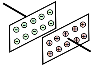
The capacitance of the capacitor is dependent upon the area of the plates - the larger the area the greater the capacitance, and also the distance between them - the greater the distance the smaller the level of capacitance.
A reverse biased diode has no current flowing between the P-type area and the N-type area. The N-type region and the P-type regions can conduct electricity, and can be considered to be the two plates, and the region between them - the depletion region is the insulating dielectric. This is exactly the same as the capacitor above.
As with any diode, if the reverse bias is changed so does the size of the depletion region. If the reverse voltage on the varactor or varicap diode is increased, the depletion region of the diode increases and if the reverse voltage on varactor diode is decreased the depletion region narrows. Therefore by changing the reverse bias on the diode it is possible to change the capacitance.

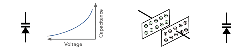
The varactor diode has a non-linear capacitance curve - the capacitance of the varactor diode is inversely proportional to the square root of the voltage across it. This means that initial changes in reverse voltage give a much greater change in capacitance, than those at higher voltages.

Varactor or varicap circuit symbol
The varactor diode or varicap diode is shown in circuit diagrams or schematics using a symbol that combines the diode and capacitor symbols. In this way it is obvious that it is being used as a variable capacitor rather than a rectifier.

When operated in any electronic circuit design, it is necessary to ensure the varactor diode remains reverse biased. This means that the cathode will be positive with respect to the anode, i.e. the cathode of the varactor will be more positive than the anode. In this way the varactor will act as a capacitor and not a diode in the circuit.
Varactor diode equivalent circuit
Like any other component, a varactor diode is not a perfect capacitor, but includes various stray elements to it. This is true of a varactor diode and as a result it is useful to be able to model the diode as an equivalent circuit. The capacitor and the stray elements need to be understood and accommodated within the electronic circuit design.

It can be seen that there are several elements to the varactor diode equivalent circuit - the different circuit elements represent the main elements that are seen when the diode is used.
The various elements are as follows:
- CJ (V): This element of the varactor diode represents the actual variable junction capacitance, which is the main required element of the diode.
- RS (V): This is the series resistance within the diode and it varies according to the voltage applied.
- CP: This circuit element represent the parasitic capacitance, mainly arising from the capacitance around the basic diode junction itself. Connecting wires within the package contribute to this.
- LP: This series capacitance mainly arises from the binding wires within the varactor diode package. Although small, it will still be noticeable in high frequency RF circuits.
The series resistance from the leads in the diode are negligible, especially as the diode operates in reverse bias, and capacitance levels are relatively small and therefore the series resistance has little effect.
Varactor diode types
When investigating high performance varactor diodes for specific RF applications, the terms, abrupt and hyperabrupt varactor diodes will often be seen.
These terms relate to the junction and hence the performance of the varactor diode - hyperabrupt diodes, as the name suggests, having a very sharp change in doping that produces a very abrupt junction - in fact it is a hyperabrupt junction!
Varactor specifications
Although the varactor diode is formed from a PN junction and has the same basic characteristics, there are some specific characteristic specifications and parameters that are needed to define its performance as a variable capacitance.
These specifications include the capacitance value and capacitance-voltage change behaviour.
The reverse breakdown characteristic is also of great importance because often quite high reverse voltages are needed to reduce the capacitance of the diode to the bottom values.
Another parameter that is very important is the quality factor or Q of the diode as this can have a significant impact on the performance of overall circuit. Low levels of Q can reduce the selectivity of a filter, or adversely impact the phase noise of an oscillator using a varactor.
Varactor diodes are very useful components that can be used in a large variety of ways, especially within RF circuits. Being able to control the capacitance within a circuit by varying a voltage has very many uses and has enabled items like phase locked loops, indirect frequency synthesizers, various types of frequency and phase modulator and many other circuits to be created.
More Electronic Components:
Batteries
Capacitors
Connectors
Diodes
FET
Inductors
Memory types
Phototransistor
Quartz crystals
Relays
Resistors
RF connectors
Switches
Surface mount technology
Thyristor
Transformers
Transistor
Unijunction
Valves / Tubes
Return to Components menu . . .

