Operational amplifiers are one of the most useful circuit blocks for analog electronic circuit design. They are easy to use and can provide some near perfect analogue circuits.
Integrated circuits, ICs have made a huge impact on the electronics scene – both analogue and digital circuits have changed the face of electronics.
Within the analogue electronics arena, none has made more difference than the operational amplifier, or op-amp. The op-amp is a differential amplifier and it is a very high performance amplifier circuit block it enables many different electronic amplifier circuits to be designed with the addition of just a handful of other components.
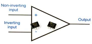
Operational amplifier circuit symbol with ICs
The operational amplifier can form the basis of a host of other circuits ranging from filters to timers, and oscillators to comparators and astables. As such the operational amplifier is one of the most versatile building blocks available to the analogue electronics circuit design engineer and hobbyist.
One of the advantages of using op amp circuits is that the electronic circuit design is often very easy whilst still yielding high performance finished circuits.
Op-amp development
Although the term operational amplifier has now become totally integrated into today's electronics terminology, it may not be realised that it dates back to a paper published in 1947. This described work that was undertaken using these amplifiers in analogue computers of the day.
Operational amplifier circuit symbol
However it was not until the 1960s that the concept of these amplifiers could be fully realised with the widespread introduction of integrated circuit technology.
In 1963, the first monolithic integrated circuit op amp was introduced. It was the µA702 from Fairchild Semiconductor which had been designed by their engineer Bob Widlar.
Later in 1965 a refinement of the µA702 was launched. Again produced by Fairchild, it was the µA709 and it was the first op amp to become widely used. It worked well, overcoming some of the issues of the ¶micro;A702, although it was necessary to externally compensate the amplifier to prevent it breaking into oscillation.
In 1968 the very famous µA741 was first introduced. This operational amplifier solved the instability issues by incorporating a small 30pF capacitor into the chip within the die. This meant that no external compensation components were required.
Adding the compensation into the actual chip enabled the 741 to be used particularly widely, and in fact it is still manufactured by some companies to this day. Also the pin configuration has also been carried over to many current day operational amplifier chips.
Since then, many operational amplifier chips have been launched offering improved performance in terms of input impedance, low offsets, low noise and the like, and they have become embedded in analogue electronics circuit design.
Now operational amplifiers have become a fundamental building block used throughout the electronics industry. Even though they have been around for some time, there seems to be little likelihood of their use falling.
What is an Op-Amp? The Basics
An operational amplifier is a very close approximation to a perfect amplifier which has infinite gain, infinite input impedance and zero output impedance.
In reality op-amps do not quite attain perfection, but with gains often in the region of 100 000 or more, input impedance levels of Megohms and more and very low output impedance levels, they come sufficiently close to enable the imperfections to be ignored in most cases.
Video: Operational Amplifier Basics
The operational amplifier has two inputs. One is called the inverting input and is marked with a "-" sign on circuit schematic diagrams. The other is the non-inverting input and this is marked with a "+" sign.
The op amp is basically a differential amplifier because the output is proportional to the difference in voltage between the two inputs.
Operational amplifier equivalent circuit
The two inputs gain their names from the way in which they amplify the signals:
Non-inverting input: The operational amplifier non-inverting input is marked by a "+" sign on the circuit diagram. It is found that a positive voltage applied to the non-inverting input will produce a positive swing at the output. If a changing waveform, such as a sine wave is applied to the non-inverting input, then it will appear in the same sense at the output. It has not been inverted.
Signal applied to the non-inverting input appears at the output in the same sense
By applying an input signal to the non-inverting input and negative feedback to the investing input, it is possible to design a circuit that does not invert the sense of the input signal.
Inverting input: The operational amplifier inverting input is marked by a "-" sign on the circuit diagram. A positive voltage applied to the inverting input will produce a negative swing at the output. Thus a sine was applied to the inverting input, will appear inverted at the output.
Signal applied to the inverting input appears at the output in the opposite sense
By applying the signal and negative feedback to the inverting input of an operational amplifier, it is possible to design a circuit where the output signal is the inverse of the input.
If the same voltage is applied to both inputs together then there should be no change at the output. In fact the output is proportional to the difference between the inverting and non-inverting inputs. It is for this reason that these amplifiers are often called differential amplifiers.
Like any electronics circuit design, those using operational amplifiers need to have a power supply. Normally op-amps are supplied using dual, i.e. positive and negative supplies. Additionally the supply lines are often not shown as they add confusion to the circuit diagram.
In most cases the operational amplifier will only need five connections for its operation - inverting, non-inverting, output and the two power rails. Very occasionally a further three may be used. These are usually for the "offset null" capability. This is used to reduce any DC offsets that may be present, and for most applications these can be ignored and left disconnected.
Operational amplifier characteristics
Operational amplifiers, op-amps have a number of basic features some of which provide advantages, others limit their performance:
Operational amplifier characteristics
Very high gain: One of the key attributes of operational amplifiers is their very high gain. Typical figures extend from around 10 000 upwards – figures of 100 000 and more are common. Although an open loop amplifier with a level of gain of this order would be of little use, op-amps are able to harness the advantages of the very high gain levels by using negative feedback. In this way the gain levels are very controllable and distortion levels can be kept very low.
The use of negative feedback is key to unlocking the power of operational amplifiers. The high gain of the op-amp combined with clever use of negative feedback means that the negative feedback network is able to control the overall performance of the op-amp circuit block, enables it to perform many different functions.
High input impedance: A high input impedance is another key aspect of op-amps. In theory their input resistance should be infinite, and the op-amps in use today come very close to this with impedances anywhere from 0.25MΩ upwards. Some using MOSFET input stages have an impedance of hundreds of MΩ.
Low output impedance: The op-amp output impedance is also important. As may be expected this should be low. In the ideal amplifier this should be zero, but in reality many amplifiers have an output impedance of less than a hundred ohms, and many very much less than this. That said, the drive capability of many IC based op-amps is naturally limited.
Common mode rejection: Another important feature of the op-amp is its common mode rejection. This refers to the situation where the same signal is applied to both inputs. For an ideal differential amplifier no output should be seen at the output under these circumstances, however the amplifier will never be perfect.
The actual common mode rejection ratio, CMMR, is the ratio between the output level when the signal is applied to both inputs compared to the output when it is applied to just one. This figure is expressed in decibels and is typically upwards of 70dB or so.
By using the common mode rejection of an operational amplifier it is possible to design a circuit that reduces the level of interference on a low level signal. The signal and return lines are applied to the two inputs and only differential signals are amplified, any noise or interference picked up and appearing on both lines will be rejected. This is often used within instrumentation amplifiers.
Limited bandwidth: The bandwidth of an op-amp can vary quite widely. An ideal amplifier would have an infinite bandwidth but as one may imagine this would be impossible create, and also very difficult to use and tame in practise. In reality op-amps have a limited bandwidth. Many of the chips used for audio applications may only exhibit their full gain over a relatively small bandwidth, after this the gain falls. Despite this most circuits act to reduce the gain, and enable this smaller level of gain to be maintained over a larger bandwidth.
Although operational amplifiers are widely used as amplifiers, they can also be as the basis of many other circuits.
As op amp circuits place feedback around the amplifier, changing this changes the properties of the overall circuit. Not only can changing the feedback alter the level of gain, but it can change the function of the circuit - it is possible to make differentiators, integrators, filters, oscillators, astable, multivibrators, and many more circuits simply by changing the feedback levels and configuration.
There are many different circuits based around op amps. These are generally easy to design and construct.
Like any other form of electronic component, operational amplifiers are available in many varieties.Op amps are available in many IC packages. Early op-amps like the µA709 were available in the circular 8 pin metal cans, whilst later op-amps were available in 8 pin dual in line packages. Multiple op-amps were also available in 14 pin DIL packages - there were even dual op-amps available in 8 pin DILs although there was no access to offset null capabilities as there were insufficient pins on the package.
As electronic components moved to surface mount pages, op amps were available in the low count packages, making them easy to drop into different circuits where required.
Operational amplifiers are also available with a wide variety of performance parameters. Part from those offering general performance characteristics, there are others that provide low noise performance, low offset, high input impedance, high frequency performance and a variety of other enhanced areas as well.
Accordingly it is possible to obtain these electronic components on formats and with performance to suit almost every requirement.
The operational amplifier is a very useful building block for analogue electronics. Being a differential amplifier circuit, it lends itself to very many areas or analogue electronics circuit design. In view of the widespread use, chips are very cheap and can be used for a wide variety of functions.
In view of their performance, easy of use and the variety of different circuits in which they can be used, operational amplifiers are used in a huge number of circuits, both as integrated circuits in the own right, and also as circuit blocks within integrated circuit chips that contain large amounts of analogue functionality.
Fact of the day: It was on this day in 1965 that Moore\'s Law was first published in an article about the future of semiconductor components. At the time, Gordon Moore who wrote about it was the head of research and development for Fairchild Semiconductor and later he went on to co-found Intel.
Quote:Science can amuse and fascinate us all, but it is engineering that changes the world. Isaac Asimov