
Transistor Specifications Explained
There are many different transistor specifications defining aspects of a bipolar transistor's performance transistor to enable an informed choice of the right transistor for any circuit .
Transistor Tutorial Includes:
Transistor basics
Gain: Hfe, hfe & Beta
Transistor specifications
Transistor and diode numbering codes
Choosing replacement transistors
There is a huge number of bipolar transistors available both leaded and surface mount devices. These have been designed to fulfil a variety of different applications in all areas of electronics.
In order to define the parameters of a transistor there are many different specifications that are used. Each of these transistor specifications define an aspect of the performance of the transistor.
Transistor manufacturers issue specification sheets for their transistors which are typically found on the Internet, although years ago engineers used to study data books to find out the information.
For electronic circuit design, selecting the right transistor will need several of the transistor parameters to match the requirements for the circuit. Therefore a variety of the parameters will need to be carefully matched.
Not all the parameters are electrical - aspects such as the size of the package, and whether the device is a surface mount transistor, i.e. surface mount device. With most PCB assembly now using surface mount technology to aid the automated electronics manufacturing of products and equipment, most transistors manufactured these days are SMD transistors.
Whilst most transistors made these days are SMD transistors because of the automated PCB assembly techniques used, there are still many leaded devices as well. Specific transistor part numbers are normally available as leaded versions and also for SMD transistors with the same electrical specifications, although aspects like the heat dissipation will differ because of the different package styles.
Transistor specification parameters
There are a number of standard parameters with abbreviations that are used to define the performance of a transistor. The definitions of these parameters are outlined in the table below:
The specifications for transistors, like any other electronics component are normally available on the website of the manufacturer. Also electronic component distributors often have details of the specifications of components, or sometimes a link to the specification on the manufacturer's website.
It is also worth noting for electronic components that can be obtained from several manufacturers, that the specifications may vary slightly between manufacturers. For any critical parameters it is wise to use the actual figures from the manufacturer whose product is being used.
Often a second source and further sources may be required to give some level of insurance against a particular supplier or manufacturer ceasing their operation and the part becoming obsolete. In this case the specification parameters for all manufacturers should be closely checked to ensure they meet the requirements for the particular electronic circuit design.
Type number
The type number of the device is a unique identifier given to each type of transistor. This enables the full data on its specifications to be checked on the manufacturers transistor datasheet to investigate its performance.
There are three international schemes that are widely used: European Pro-Electron scheme; US JEDEC (numbers start with 2N for transistors); and the Japanese system (numbers start with 2S).
Apart from just giving a standardised type number to the transistors, these schemes can provide information about the transistor performance. The European Pro-Electron scheme is particularly good for this as it distinguishes between different types of transistor, for example a BC109 is a silicon audio frequency low power transistor, and a BFR90 is a low power RF transistor.
However when using automated PCB assembly techniques and surface mount devices, it is found that many transistors are too small to carry the full number that might be used in a data sheet. As a result, a rather arbitrary coding system has developed, whereby the device package carries a simple two or three character identification code.
This can normally be accommodated on the small surface mount diode packages. However, identifying the manufacturers' type number of an SMD diode from the package code may not be easy at first sight. There are some useful SMD codebooks available that provide the data for these devices.
Polarity:
There are two types of transistor: NPN transistors and PNP transistors. It is important to choose the correct type otherwise all the circuit polarities will be wrong.
The NPN transistors are more widely used. Like for like they offer better performance than PNP transistors because electrons are the majority carriers and their mobility is higher than that of holes which are the majority carriers in PNP transistors. The basic circuits for NPN transistors also fit well with the negative earth normally used in DC systems.
Material
One key transistor specification which will be given for any transistor is the material from which t is manufactured. The main type of material used for semiconductor devices is silicon.
Although other materials like germanium and gallium arsenide are available, silicon is the most popular because it is cheaper to process and in addition to this, the processes are more advanced than for other materials. As it is used for many other semiconductor devices, there are many benefits of scale and technology available.
Silicon offers good overall performance with a base emitter junction turn on voltage of around 0.6 volts - it is 0.2 to 0.3 volts for germanium.
Collector to base breakdown voltage, specification, VCBO
The VCBO parameter is the maximum collector base voltage - again it is generally measured with the emitter left open circuit. This value should not be exceeded in the operation of the circuit.
This parameter is important because some leakage current will flow between collector and base, causing the part to heat up. Alternatively excessive voltage can damage the collector base junction. As terminal damage can occur to the bipolar transistor, this rating should not be exceeded and ideally the transistor should be run with a good margin in hand.
In operation the collector-base junction is reverse biassed, and a small reverse current will flow (ICBO. As the reverse voltage is increased the electric field in the depletion region of the collector base junction increases, and the reverse current starts to rise as minority carriers gain sufficient energy to generate hole electron pairs which then increase the reverse current. Eventually avalanche breakdown occurs. This limits the maximum voltage that can be applied to the transistor.
VCBO is typically higher than VCEO because with the base terminal of the BJT open, any leakage current will also be the same as externally applied base current, and this is amplified by the transistor. This will cause even more current to flow through the device, heating it up and for this reason, VCEO is often lower than VCBO.
Collector to emitter breakdown voltage specification, VCEO
This transistor specification is the maximum voltage that can be placed from the collector to the emitter. It is normally measured with the base open circuit - hence the letter "O" in the abbreviation. During the electronics circuit design stage it is essential to ensure that this value is not be exceeded in operation, otherwise damage may occur. Ideally the transistor should be operated with a good margin in hand.
Often the maximum voltage should only be allowed to rise to 50 or 60% of the maximum value for reliable operation. Note that for circuits using inductors in the collector circuit, the collector voltage may rise to twice the rail voltage.
If the voltage applied between the collector and emitter terminals is high, and increased number of carriers start to diffuse into the collector region from the base. This causes the base emitter diode in the bipolar transistor to start to become forward biassed, and this causes current to flow between the collector and emitter, even though no external base current has been applied. When a certain voltage, VCEO, is reached the transistor can fully turn on, and in some cases this can result in terminal damage to the device.
Collector current specification, IC
The collector current specification of the transistor is normally defined in milliamps, but high power transistors may be quoted in amps.
The important parameter is the maximum level of collector current. This figure should not be exceeded otherwise the transistor may be subject to damage.
Collector emitter saturation voltage, VCEsat
The collector emitter saturation voltage, i.e. the voltage across the transistor (collector to emitter) when the transistor is turned hard on. It is normally quoted for a particular base and collector current values.
Under these circumstances the voltage between the collector and emitter is smaller than that across the base emitter junction - often it is around 0.2 volts.
Forward current gain, hFE & hfe
This is the current gain for a transistor expressed as an h parameter or hybrid parameter. The letter "f" indicates that it is a forward transfer characteristic, and the letter "e" indicates it is for a common emitter configuration. The value for hfe is approximately the same as β.
Two versions of this parameter are seen: hFE refers to the parameter measured under DC conditions, whereas hfe refers to the parameter for AC signals.
Transition frequency specification, FT
Frequency Transition - this transistor specification details the frequency where current gain falls to unity. The transistor should normally be operated well below this frequency.
Device power dissipation, Ptot
Total power dissipation for the device. It is normally quoted for an ambient external temperature of 25°C unless other wise stated. The actual dissipation across the device is the current flowing through the collector multiplied by the voltage across the device itself.
Package type
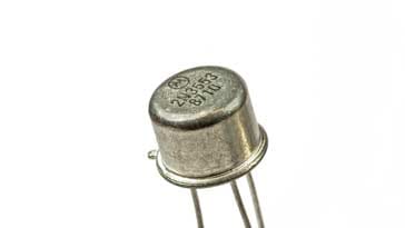
Transistors can be mounted in a variety of packages according to their applications. There are the standard leaded devices that appear in a variety of packages - these packages normally conform to JEDEC standards and start with the letters TO, standing for transistor outline. This is followed by a hyphen and a numeral which is typically up to three digits.
Popular leaded component sizes include TO5 (metal case, cap diameter of 8.1 mm), TO18 (metal case with cap diameter of the cap is 4.5-4.95mm) and TO92 (also known as SOT54, plastic case off varying sizes but straight line lead spacing of 1.27mm).
Surface mount transistors, SMD transistors are used in vast quantities because most electronics manufacture and PCB assembly is undertaken using automated techniques and surface mount technology lends itself to this. Popular sizes include the SOT-23 and SOT-223 outlines.
Other points to consider
Although the data sheet parameters are very important, there are also several other aspects to the selection of electronics components, and in this case transistors, for a particular circuit design.
These additional points, look at several points outside the data-sheet. These points can be just as important as the data-sheet parameters in the choice of the right component.
By considering these points, the best transistors can be chosen, not only in terms of the basic parameter specifications, but also in terms of other factors that are equally or even more important.
Key Aspects of Component Selection:
Although it is possible to make many decisions about selecting the right component for a circuit design from the datasheet parameters, this is not the only basis for selecting the right components as there are several other attributes not in the data-sheets that need to be embodied in any decision. These are equally important as the basic specification parameters, but not always taken into account. In our web page, we reveal the key additional aspects to consider so that the overall best choice is made.
Read more about secrets of selecting components.
There are many different elements to transistor specifications, both both leaded and surface mount transistors. To meet the demand for electronics manufacture there is a huge variety of transistors from which to choose. However it is still relatively easy to choose a transistor when using a basic knowledge of the different transistor specifications and parameters.
For general purpose applications many transistors will suffice, but for more specialised applications it is essential to select the right type of transistor.
More Electronic Components:
Batteries
Capacitors
Connectors
Diodes
FET
Inductors
Memory types
Phototransistor
Quartz crystals
Relays
Resistors
RF connectors
Switches
Surface mount technology
Thyristor
Transformers
Transistor
Unijunction
Valves / Tubes
Return to Components menu . . .


