
Amplitude Modulation, AM Index & Modulation Depth
Modulation Index and Modulation Depth are key issues for the effectiveness of amplitude modulated, AM signals.
Amplitude Modulation, AM Tutorial Includes:
Amplitude modulation, AM
AM basic theory & formulas
AM bandwidth & sidebands
Modulation index & depth
AM efficiency
AM demodulation / detection
Diode detector
Synchronous detector
AM modulators
Single sideband, SSB
SSB demodulation
Modulation formats:
Modulation types & techniques
Frequency modulation
Phase modulation
Quadrature amplitude modulation
It is possible to vary the level of modulation applied to an amplitude modulated signal. This is an important factor for broadcast and two way radio communications applications.
If little modulation is applied then the audio (assuming it us an audio transmission) will be difficult to hear and this will make the signal less easy to listen to.
However if too much is applied, distortion can result and signals will not be easy to listen to and interference will increase. This interference could affect users on nearby frequencies or channels.
As a result of this it is necessary to have a way of defining the level of modulation applied to an amplitude modulated signal, and monitoring the level.
Two figures are used for this, namely the amplitude modulation, AM modulation index, and the modulation depth. Both are related, but they have slightly different meanings.
AM modulation index basics
The term, Modulation Index, is used for a number of forms of modulation, including AM, and obviously for the different types of modulation, there are different methods of obtaining the index.
It is useful to define the modulation index for amplitude modulation. Accordingly it is worth defining exactly what the modulation index actually is.
Amplitude Modulation Index definition:
The modulation index of an amplitude modulated signal is defined as the measure or extent of amplitude variation about an un-modulated carrier.
In other words the amplitude modulation index describes the amount by which the modulated carrier envelope varies about the static level.
This can be expressed in mathematical terms as below:
Where:
A = the carrier amplitude.
M = the modulation amplitude and is the peak change in the RF amplitude from its un-modulated value.
Using the equation above it can be seen that a modulation index of 0.75 means that the signal will increase by a factor of 0.75 and decrease to 0.25 of its original level.
A modulation index of 1 is the maximum level of modulation that can normally be applied and occurs when the envelope increases by a factor of 1, i.e. twice the steady state value, and falls to zero.
AM modulation depth basics
The amplitude modulation AM modulation depth figure is complementary to the modulation index.
Typically the modulation depth is the amplitude modulation index expressed as a percentage.
In this way an AM modulation index of 0.75 would be expressed as a modulation depth of 75%.
In reality the terms AM modulation index and the AM modulation depth are often used interchangeably, so there are often no hard and fast rules regarding their use.
AM modulation index examples
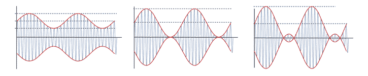
It is helpful to see some examples of amplitude modulated waveforms with different levels of modulation index.
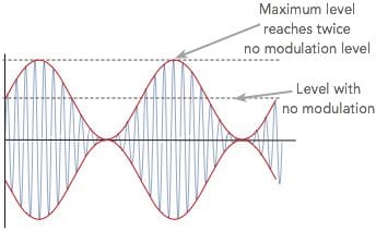
The most widely seen modulation level is for a signal that has 100% modulation. Under these circumstances the signal level falls to zero and rises to twice the value with no modulation.
In this case the voltage rises to a maximum of twice the normal level – this means that the power will be four times that of the quiescent value, i.e. 22 the value of the no modulation level.
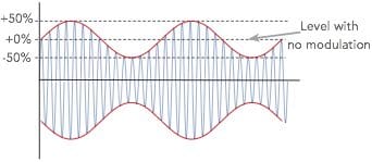
If less than 100% modulation is applied, then the carrier will not fall to zero, no will it rise to twice the level, but the deviation will be less than this from the quiescent level.
The diagram below shows a level of 50% modulation, but the principle holds good for any value between 0 and 100% modulation.
Levels greater than 100% modulation
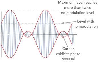
If the level of modulation is raised up above a modulation index of 1, i.e. more than 100% modulation this causes what is termed over-modulation.
The carrier experiences 180° phase reversals where the carrier level would try to go below the zero point. These phase reversals give rise to additional sidebands resulting from the phase reversals (phase modulation).
These sideband caused by the phase reversal extend out, in theory to infinity. This can cause serious interference to other users if not filtered.
Broadcast stations using amplitude modulation take measures to ensure that the carriers or signals for their transmissions never become over modulated. The transmitters incorporate limiters to prevent more than 100% modulation.
They also normally incorporate automatic audio gain controls to keep the audio levels such that near 100% modulation levels are achieved for most of the time. In this way the signal sounds clearer and stronger when demodulated.
The audio processor may also clip the audio if it becomes very close to the 100% modulation level. This will ensure that the carrier is not over-modulated.
If an audio clipper is used, then this will need to be followed by an audio filter as clipping introduces audio harmonics which may fall outside the permitted audio bandwidth for the transmission.
If the audio went un-filtered, then the high audio frequencies would cause the overall transmitted signal to have a wide bandwidth as the bandwidth of an amplitude modulated signal is twice that of the highest audio frequency.
Many stations use very sophisticated audio processors to provide the maximum level of audio on the carrier, to provide the "loudest" audio without over modulating the carrier.
Monitoring modulation level
For any transmitting station using amplitude modulation, it is necessary to ensure that the signal is not over-modulated. This is particularly important for AM broadcast stations where there will be strict limits on the levels of interference that are generated. If the modulation levels are too high, then the signal may be over-modulated and interference caused.
For other forms of radio communication using amplitude modulation such as aviation communications, the level must also be limited so that the carrier is not over-modulated causing interference to other users occupying nearby channels.
Regulators for broadcasters take a dim view of stations that might cause high levels of interference, and users will also suffer.
Even though audio limiters will be incorporated, it is still necessary to be able to monitor the set-up and ensure that everything is working correctly.
For applications where AM is used for two way radio communications, the walkie-talkie's are most likely to have been set within manufacture, or the design will intrinsically limit the modulation level and continuous monitoring will not be needed.
Even the base radio communications equipment is unlikely to need and setting or calibration. As power levels are lower the issues are not as crucial as for broadcasting.
There are several methods that can be used to ensure that the transmitter is operating correctly:
Oscilloscope: Using an oscilloscope it is possible to monitor the output signal. Especially in the case of high power transmitters, the connection can be made via a special coupler that will sample the outgoing signal, but at a much reduced level for the oscilloscope. An easy way to obtain a sample is to wind a pickup loop and connect it to the the vertical input of the oscilloscope.
Depending on the location of the oscilloscope and the signal levels present, a short antenna with a tuned circuit may be used. This approach works well in the vicinity of the transmitter where radiation levels will be relatively high.
The envelope can then be monitored to ensure that it does cross the zero signal line - this is where the phase reversals occur which give rise to wide-band interference noise.
- Spectrum analyzer: Using a spectrum analyzer to monitor the modulation index / depth, the analyzer will sample the signal and display its spectrum on the display. The analyzer will be able to see the signal and monitor whether any components fall outside the allotted bandwidth for the signal.
Real time spectrum analyzers will be better at monitoring any transient effects, although they are considerably more costly.
- Modulation meter: For continual monitoring, it is much easier to use a modulation meter. These meters provide an indication of the modulation index or modulation depth on a numerical display. They will not provide as much information, but are often quite adequate for ongoing monitoring.
These different methods can be used as appropriate to monitor continuously or from time to time as appropriate.
The modulation index and modulation depth figures are widely used when describing the modulation applied to an amplitude modulated signal. Too little and the signal will not appear to have sufficiently loud audio. Too much and the signal will create interference well beyond the channel on which it is operating.
More Essential Radio Topics:
Radio Signals
Modulation types & techniques
Amplitude modulation
Frequency modulation
OFDM
RF mixing
Phase locked loops
Frequency synthesizers
Passive intermodulation
RF attenuators
RF filters
RF circulator
Radio receiver types
Superhet radio
Receiver selectivity
Receiver sensitivity
Receiver strong signal handling
Receiver dynamic range
Return to Radio topics menu . . .


