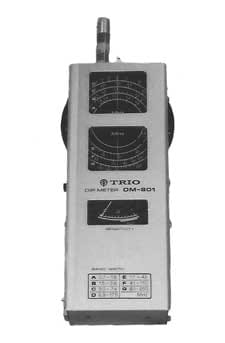
How to Use a Dip Meter, GDO
One of the advantages of the dip meter or grid dip oscillator, GDO is that it is very easy to use.
Dip Meter Tutorial Includes:
Dip meter / GDO basics
How to use a dip meter / GDO
Using GDO to measure inductance
Using GDO to measure capacitance
Measuring antenna resonant frequency
Measuring feeder electrical length
One of the easiest measurements to make using a dip meter or GDO is the resonant frequency of a resonant circuit.
Often the circuit under test will be in the form of LC coil and inductor circuit. Typically this may be a tuned circuit in an item of equipment such as a transmitter or receiver.

How to use a dip meter GDO
Using a dip meter is very straightforward, but there are a few precautions to observe if good results are to be obtained.
The first step is to select the required coil for the frequency range needed. Each of the coils will be labelled with the range that it will enable the GDO to cover. This should be inserted firmly into the socket for the coils which is typically located at the top of the instrument.
It is also necessary to select the mode in which the dip meter / grid dip oscillator will be used. There are two basic modes:
- Monitor / wavemeter mode: In this mode the oscillator is turned off and the dip meter is used as a wavemeter to monitor radiation. In this mode it may be used as an absorption wavemeter. If placed sufficient close to a source of radiation, e.g. from a transmitter, then it will register a signal on the meter as it is tuned to the signal frequency. Typically dip meters are designed to include a headphone socket which enables the amplitude modulation on the signal to be monitored. When using the dip meter in this mode care should be taken with the levels of radiation that may be present, and also with any voltages that may be present on the transmitter.
- Oscillator mode: The oscillator or dip mode is the most useful mode for the grid dip oscillator / dip meter.

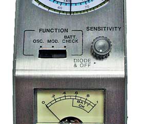
Controls seen on a typical Dip Meter
Assuming the dip meter is to be used in its oscillator or dip meter mode, then the test instrument should be turned on. The sensitivity control should be adjusted to give a deflection close to full scale, but the meter deflection will vary over the range and therefore the optimum level should be chosen for the frequencies needed - possibly adjusting the sensitivity as the band is swept.
When checking out a resonant circuit it is normal to place the axis of the coil of the dip meter in line with the axis of the coil of the resonant circuit. In this way the best coupling and the largest dip is seen. This actually provides inductive coupling between the two circuits.
It is found that the action of the second coil, i.e. the one under test, pulls the dip meter oscillator off frequency and thereby introducing error on the reading.
This is a major source of in accuracy, but it can be reduced. Once the dip has been found the coupling between the two circuits can be reduced by moving the dip meter away - the dip will reduce, but the dip meter oscillator will be pulled less.
The dip meter can be moved away to a point where the dip can be located, but the coupling and hence the pulling of the circuit is optimised to give the best reading. The frequency of the dip is repeatedly checked during this process.
As a rough rule of thumb, it is best to move the two coils away from each other so that the dip is around 25% of the maximum meter reading. This gives a sufficiently large dip to be seen and locate the bottom of the dip, whilst also keeping the coupling to a minimum.
Other grid dip meter measurements
Apart from the basic measurement of the resonance frequency of a tuned circuit, it is possible to use grid dip meters for a variety of other measurements. Some of these measurements are outlined below and there are further more detailed pages outlining how to use a grid dip meter for these measurements.
- How to use a grid dip meter to measure unknown inductor: This measurement requires the use of a known capacitor to use with the inductor to make a resonant circuit. The frequency of this is measured using grid dip oscillator / dip meter and the value of the inductor calculated. . Read more about measuring inductance of unknown inductor.
- How to use a grid dip meter to measure unknown capacitor: This measurement requires the use of a known value inductor to use with the capacitor to make a resonant circuit. The frequency of this is measured using dip meter / grid dip oscillator and the value of the capacitor is calculated. . Read more about measuring capacitance of unknown capacitor.
- How to use a grid dip meter to estimate the Q of an inductor: This method is fairly rough and ready but entails using the dip meter to tune either side of the resonant frequency to a point where the dip is reduced by about 30%. These two frequencies can be used to give a rough estimate of the Q of the circuit.
- How to use a grid dip meter to measure resonance of an antenna: The resonant frequency of an antenna can be determined using a grid dip oscillator or dip meter by coupling the meter to the antenna and the searching for the lowest dip. Read more about measuring an antenna resonant frequency.
- How to use a grid dip meter to find electrical length of feeder: This measurement entails sorting the far end of the feeder and coupling the dip meter to the feeder. Findingt he dip shows the resonant frequency of the feeder from which the electrical length can be determined. Knowing the velocity factor can enable the physical length to be estimated as well. Read more about measuring electrical length of a feeder.
Problems with GDO dip?
On occasions some issues may be encountered with the dip obtained using a grid dip meter / GDO. It is not uncommon to experience issues, but these can normally be overcome without too much difficulty.
Some of the grid dip meter issues include:
- Dip does not reduce as coils moved apart: In some instances it may be that as the coils are moved apart the dip on the grid dip meter does not reduce. This can occur for a number of reasons. The main one is that it is a dip that occurs within the dip meter itself. If this is the case, then it is necessary to find the real dip elsewhere. Alternatively if the dip is expected in the region of the false dip, then another coil with an overlapping range may be used.
- No dip is found: If no dip is found and there is sufficient coupling between the grid dip meter and the circuit under test then the resonance point must be outside the range of the coil being used on the meter. In this case another coil / range should be used. It is also necessary to check that there is sufficient coupling between the two circuits.
Normally measurements can be made quite easily and no issues are found. However when they do occur, they are normally overcome relatively easily.
More Test Topics:
Data network analyzer
Digital Multimeter
Frequency counter
Oscilloscope
Signal generators
Spectrum analyzer
LCR meter
Dip meter, GDO
Logic analyzer
RF power meter
RF signal generator
Logic probe
PAT testing & testers
Time domain reflectometer
Vector network analyzer
PXI
GPIB
Boundary scan / JTAG
Data acquisition
Return to Test menu . . .


