
How to Measure Resistance with a Multimeter
Knowing how to measure resistance with multimeter is easy - here we provide some guidelines about how to make resistance measurements with a multimeter & provide some hints & tips.
Multimeter Tutorial Includes:
Test meter basics
Analogue multimeter
How does an analogue multimeter work
DMM digital multimeter
How a DMM works
DMM accuracy & resolution
How to buy best digital multimeter
How to use a multimeter
Voltage measurement
Current measurements
Resistance measurements
Diode & transistor test
Fault finding transistor circuits
One important measurement that can be made with a multimeter is a resistance measurement. Not only can these be made to check the accuracy of a resistor, or check it is functioning correctly, but resistance measurements can be required in many other scenarios as well.
It may be to measure the resistance of an unknown conductor, or it may be to check for short circuits and open circuits.
In fact there are many instances where measuring resistance is of great interest and importance. In all these cases a multimeter is an ideal piece of test equipment for measuring resistance
Resistance measurement basics
When measuring resistance, all musltimeters use exactly the same principle whether they are analogue multimeters or digital multimeters. In fact other forms of test equipment that measure resistance also use the same basic principle.
The basic idea is that the multimeter places a voltage at the two probes and this will cause a current to flow in the item for which the resistance is being measured. By measuring the resistance it is possible to determine the resistance between the two probes of the multimeter, or other item of test equipment.
How to measure resistance with an analogue multimeter
Analogue multimeters are good at measuring resistance, although they are a few points to note about the way in which it is done.
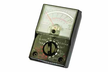
The first point to note is that as the meter itself responds to current flowing through the component under test. A high resistance corresponds to a low current and the meter needle settles on on the left hand side of the dial, and a low resisatnce corresponds to a higher current and the meter needle deflects more so it appears on the right hand side of the dial as shown below.
It will also be noticed that the calibrations become much closer together as the resistance becomes higher, i.e. on the left hand side of the dial.

Another aspect of using an analogue multimeter for measuring resistance is that the meter needs to be "zero'ed" before making a measurement. This is done by connecting the two probes together so that there is a short circuit, and then using the "zero" control to give full scale deflection on the meter, i.e. zero ohms.
Each time the range is changed, the meter needs to be zero'ed as the position may change from one range to the next. The meter needs to be zero'ed because the full scale deflection will change according to aspects such as the state of the battery.
There are a few simple steps required to make a resistance measurement with an analogue multimeter:
- Select the item to be measured: This may be anything where the resistance needs to be measured and estimate what the resistance may be.
- Insert the probes into the required sockets Often a multimeter will have several sockets for the test probes. Insert these or check they are already in the correct sockets. Typically these might be labelled COM for common and the other where the ohms sign is visible. This is normally combined with the voltage measurement socket.
- Select the required range The analogue multimeter needs on and the required range selected. The range selected should be such that the best reading can be obtained. Normally the multimeter function switch will be labelled with the maximum resistance reading. Choose the one where the estimated value of resistance will be under but close to the maximum of the range. In this way the most accurate resistance measurement can be made.
- Zero the meter: The meter needs to be zero'ed. This is done by firmly placing the two probes together to give a short circuit and then adjusting the zero control to give a zero ohms (full scale deflection) reading. This process needs to be repeated if the range is changed.
- Make the measurement With the multimeter ready to make the measurement the probes can be applied to the item that needs to be measured. The range can be adjusted if necessary.
- Turn off the multimeter Once the resistance measurement has been made, it is wise to turn the function switch to a high voltage range. In this way if the multimeter is used to again for another type of reading then no damage will be caused if it is inadvertently used without selecting the correct range and function.
Analogue multimeters are ideal pieces of test equipment for measuring resistance. They are relatively cheap and they offer a reasonably good level of accuracy and general performance. They normally provide a level of accuracy that is more than sufficient for most jobs.
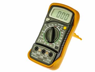
How to measure resistance with an digital multimeter, DMM
Measuring resistance with a digital multimeter is easier and faster than making a resistance measurement with an analogue multimeter as there is no need to zero the meter. As the digital multimeter gives a direct reading of the resistance measurement, there is also no equivalent of the reverse reading found on the analogue multimeters.
There are a few simple steps required to make a resistance measurement with a digital multimeter:
- Select the item to be measured: This may be anything where the resistance needs to be measured and estimate what the resistance may be.
- Insert the probes into the required sockets Often a digital multimeter will have several sockets for the test probes. Insert these or check they are already in the correct sockets. Typically these might be labelled COM for common and the other where the ohms sign is visible. This is normally combined with the voltage measurement socket.
- Turn on the multimeter
- Select the required range The digital multimeter needs on and the required range selected. The range selected should be such that the best reading can be obtained. Normally the multimeter function switch will be labelled with the maximum resistance reading. Choose the one where the estimated value of resistance will be under but close to the maximum of the range. In this way the most accurate resistance measurement can be made.
- Make the measurement With the multimeter ready to make the measurement the probes can be applied to the item that needs to be measured. The range can be adjusted if necessary.
- Turn off the multimeter Once the resistance measurement has been made, the multimeter can be turned off to preserve the batteries. It is also wise to turn the function switch to a high voltage range. In this way if the multimeter is used to again for another type of reading then no damage will be caused if it is inadvertently used without selecting the correct range and function.
Digital multimeters are ideal pieces of test equipment for measuring resistance. They are relatively cheap and they offer a high level of accuracy and general performance.
General precautions when measuring resistance
As with any measurement, when measuring resistance, there are some precautions to observe. In this way damage to the multimeter can be prevented, and more accurate measurements can be made.
- Measure resistance when components are not connected in a circuit: It is always advisable not to measure the resistance of an item that is in a circuit. It is always best to make the measurement of the component on its own out of the circuit. If a measurement is made in-circuit, then all the other components around it will have an effect. Any other paths that will allow current to pass will affect the readings, making them inaccurate to some degree.
- Remember to ensure the circuit under test is not powered on Under some circumstances it is necessary to measure resistance values actually on a circuit. When doing this it is very important to ensure the circuit is not powered on. Not only will any current flowing in the circuit invalidate any readings, but should the voltage be high enough, the current resulting could damage the multimeter.
- Ensure capacitors in a circuit under test are discharged. Again when measuring resistance values in a circuit, it is necessary to ensure that any capacitors in the circuit are discharged. Any current that flows as a result of them will cause the meter reading to be altered. Also any capacitors in the circuit that are discharged may charge up as a result of the current from the multimeter and as a result it may take a short while for the reading to settle.
- Remember diodes in a circuit will cause different readings in either direction When measuring resistance in a circuit that includes diodes the value measured will be different if the connections are reversed. This is because the diodes only conduct in one direction.
- Leakage path through fingers can alter readings in some cases. When making some resistance measurements it is necessary to hold a resistor or component onto the multimeter test probes. If high resistance measurements are being made the leakage path through the fingers can become noticeable. Under some circumstances the resistance path through fingers can be measured at just a few megohms, and as a result this can become significant. Fortunately the levels of voltage used in most multimeters when measuring resistance is low, but some specialised meters may use much higher voltages. It is wise to check.
Measuring resistance with a multimeter is very easy and convenient. When looking at how to measure resistance, it is quite straightforward for both analogue and digital multimeters and the process is virtually the same in both instances, although readings may not be quite as easy to take if the resistance is high and the measurement needs to be taken where the calibrations are close together. Nevertheless whatever test equipment is used , resistance is easy to measure.
More Test Topics:
Data network analyzer
Digital Multimeter
Frequency counter
Oscilloscope
Signal generators
Spectrum analyzer
LCR meter
Dip meter, GDO
Logic analyzer
RF power meter
RF signal generator
Logic probe
PAT testing & testers
Time domain reflectometer
Vector network analyzer
PXI
GPIB
Boundary scan / JTAG
Data acquisition
Return to Test menu . . .


