
Transistor Circuit Test & Fault Finding using a Multimeter
Finding faults in transistor circuits with a multimeter can be simplified by adopting a logical approach along with using some hints and tips gained from experience.
Multimeter Tutorial Includes:
Test meter basics
Analogue multimeter
How does an analogue multimeter work
DMM digital multimeter
How a DMM works
DMM accuracy & resolution
How to buy best digital multimeter
How to use a multimeter
Voltage measurement
Current measurements
Resistance measurements
Diode & transistor test
Fault finding transistor circuits
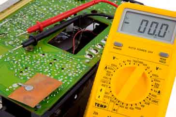
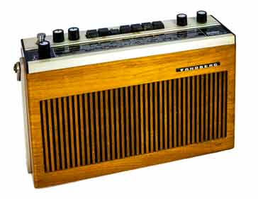
One of the main uses for multimeters whether they are analogue multimeters or digital multimeters, DMMs is to test and fault find circuits like those in a transistor radio. Multimeters are ideal items of test equipment for finding many faults in a transistor or other form of electronic circuit.
However to use a multimeter to test a circuit and find faults it is necessary to have a little knowledge about the circuit, and also to adopt a logical approach in tracking down any faults that may exist.
A little experience knowing the likely faults and failures that occur within the different types of equipment also helps. The test meter can be used to test these and often locate the fault very quickly.
Both analogue multimeters and digital multimeters can be used for these simple tests - the choice normally being made by what is available.
A word of warning
Some electrical and electronics equipment may be mains powered. Only qualified persons should attempt to repair mains powered equipment or equipment that contains high or hazardous voltages. Also, only the right test equipment, with the right certifications and capable of handling high voltages should be used where high voltages are present. High voltages can kill so be warned!
Look for obvious faults
The first step when looking at tracing any faults and testing a transistor circuit of any sort is to look for the obvious or major faults. This is one of the key stages in repairing any equipment.
Fortunately most faults with electronics equipment such as transistor radios are relatively easy to find - many are quite obvious and some may not even need any test equipment. They often arise from movement and physical damage, so it is often easy to find these faults and issues.
Accordingly the first step in any fault finding is to look for the major problems.
Check the supply to the circuit: The first steps in checking the circuit are to ensure that it has power being supplied to it. This is easily done using a multimeter set to a voltage range. Measure the voltage using a test meter at the points where the supply enters the circuit board. If the multimeter indicates that there is no supply voltage then there can be a number of possibilities to investigate:
Battery could be flat if the equipment is battery powered. Sometimes it may be obvious as the battery may be leaking. If this is the case remove the battery and clean any residue that may have leaked onto the battery holder and in particular the contacts. The residue can cause the contacts to become corroded, so it is necessary to clean the contacts well. Take care not to touch the residue as it can be corrosive
If the battery condition is not so obvious, then a simple voltage measurement using the test meter can highlight if this is an issue. Check the voltage with the test meter when the radio is turned on. If the battery cannot supply the current required, then the voltage will fall as the radio is switched on.
- On-off switch faulty. This can be checked by disconnecting any power source - the power lead must be removed from the power to completely isolate the equipment. Then check for continuity across the switch, checking it on both on and off positions - use the Ohms range on the multimeter for this. Also remember that the switch may switch both sides on the incoming power, i.e. live and neutral, and either of these sides of the switch could be non-functional.
- If a fuse is present, then it is worth checking tis. Ideally remove the fuse and check for continuity with the multimeter. Its resistance should be less than an Ohm.
- Corroded connector. One common problem is that connectors become corroded with time and connections can become very poor, especially of the equipment has not been used for some time. To overcome this it can help to unplug and then re-mate the connector.
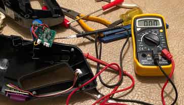
- Check for any broken wiring that would prevent the power reaching the circuit board. With time and movement of the equipment, leads can become fractured. One particular area can be the battery lead - these leads are particularly prone to damage as the need to be moved and if the battery has been replaced in a rough manner this could result in a lead being broken. Check for visual signs, and also use the multimeter Ohms range as well.
- Check the outputs from the board: In the same way that broken connections may exist for the power line, the same may be true of the outputs from the board. Again it is worth checking any connectors that may have corroded or oxidised with time, and check for any broken connections.
Check the inputs to the circuit: Likewise, if the signal inputs are not reaching the board then it will not be able to perform. Again any switches, and connectors along with any broken wires should be checked. Often a multimeter can be used to check the continuity of the wires, but first ensure there is no power applied to the circuit.
Check operation of any other switches: The main on-off power switch is obviously important, but so too are any other switches in the equipment.
Check operation of other switches: Although the power switch mentioned above could be one possible issue, there may be other switches in the circuit that could cause the equipment to malfunction. Over time switches can fail as dirt and corrosion accumulate on the switch contacts. Dirt and tar can be a particular problem if the equipment is in an environment where smokers are present.
It is possible to check the switch using a multimeter, but sometimes, simply actuating the switch can help clean the contacts. Switch cleaner can also help.
By using a multimeter for the fault finding, it is possible to find many of the obvious faults that can occur. If the problem cannot be found, and it appears that the correct power is reaching the transistor circuit, and the inputs are all connected and present as well as the output lines being intact, then further fault finding on the transistor circuit board itself may be needed. Again a multimeter can assist in this.
Homing in on where the fault is located
If the fault is not one of the very obvious ones, then a little more circuit knowledge may be required along with some simple test instruments. The test meter is one of the key pieces of test equipment, but a few other tricks of the trade can be used for the testing.
One of the key techniques is to adopt a systematic approach so that it is possible to home in on the issue.
Often it is best to work from the edge inwards. For radios it is often good to work from the loudspeaker backwards, as it is possible to inject signals and see how they come out of the speaker, working progressively back through the radio to see where the signal does not work any more.
For other items it may be best to work the other way, but each needs to be determined according to the item being repaired.
Looking at the example of the transistor radio, one test could be with the radio operating touch the probe of the test meter onto the centre pin of the volume control (with the volume control turned part way up. As the multimeter probe is touched onto the centre pin, a small click should be heard.
If some other form of audio signal injector, signal generator, etc is available, then this too could be used, but often the test meter probe is much easier for a quick check.
If the audio amplifier works, then it is necessary to move back a stage. Most radios are superheterodyne radios, so the IF amplifier stages can be checked next. Set a signal generator to the intermediate frequency (typically about 455 kHz for old AM broadcast radios and 10.7MHz for FM broadcast radios). Introduce modulation if possible, otherwise listen for the carrier.
Note on the Superheterodyne Radio:
The superheterodyne radio uses a technique where incoming signals are mixed or multiplied with the signal from an internally generated local oscillator. In this way the signals can be converted in frequency to an intermediate frequency where they can be filtered. By using a variable frequency local oscillator, a fixed frequency intermediate frequency filter can be used.
Read more about the Superheterodyne Radio.
If the LO works, then the issue is most likely in the RF stages. Again, inject a signal and see what happens. It could be the stage does not work at all, or it may be insensitive.
By adopting a logical approach like that for the radio in the example above, it is possible to home in on the area of the fault. The actual approach will depend upon the item under test, but often expensive test equipment is not required, and a test meter such as an analogue test meter or digital multimeter can be used.
Once the area in which the fault is located has been found, then testing of the circuit using a multimeter can start.
Expected voltages in a transistor circuit
When testing a particular transistor circuit, a multimeter can be used to determine if the voltages around the circuit are correct. To test and fault find a particular transistor circuit, it is necessary to have an idea what the steady voltages should be. The circuit below is a typical basic transistor circuit. Many circuits are similar to it, and it provides good starting point to explain some of the points to note.

The circuit shows several of the points where the voltage can be measured in a circuit. Most of them are measured with respect to ground. This is the easiest way to make a voltage measurement because the "common" or negative probe can be clipped to a suitable ground point (many black probes used for the negative line have a crocodile or alligator clip for this purpose). Then all the measurements can be made relative to ground.
There are normally a number of points around a transistor circuit that are easy to measure, and the expected voltages can be anticipated for the most part if a few assumptions are made:
- Assume the circuit is operating in a linear mode, i.e. it is not a switching circuit.
- Assume the circuit is operating in a common emitter mode as shown in the diagram.
- Assume the circuit has a resistive collector load.
If the assumptions above are true, then the following voltages can be expected. If not then allowances need to be made for the changes.
- The collector voltage should sit at approximately half the rail voltage. More specifically it should sit at half the rail voltage less the emitter voltage. In this way the greatest voltage swing can be obtained. If the transistor has an inductive load, as in the case of the intermediate frequency amplifier in a radio which may have an IF transformer in the collector circuit, then the collector should sit at virtually the same voltage as the rail voltage.
- The emitter voltage should sit at around a volt or two. In most class A common emitter circuits an emitter resistor is included to give some DC feedback. The voltage across this resistor is typically a volt or so.
- The base voltage should sit at the PN junction turn on voltage above the emitter. For a silicon transistor, which is the most common type, this is around 0.6 volts.
Indications of the types of voltage expected can be seen on the circuit diagram.
In addition to this, there are many other types of circuit which may need fault finding. Switching circuits are quite common these days where transistors are used to drive other elements such as relays or other devices. These do not operate in a linear mode. Instead all voltages are either on or off. The collector voltage will either be approximately zero when the transistor is on, and approximately the rail voltage when off. The emitter will usually be connected to ground, and the base voltage will be high, i.e. approximately 0.6 volts for a silicon transistor when the transistor is on (i.e. collector near zero), and low, (zero volts) when the transistor is off and the collector is high.
A test meter, either an analogue multimeter or a digital multimeter is an ideal piece of test equipment to help with fault finding an electronics transistor circuit. Often circuits like transistor radios fail after they have been used for many years, and it is useful to be able to mend them Also when constructing equipment, circuits do not always work first time and it is necessary to fault-find these circuits. While it will not be possible to solve all problems using a multimeter, it is one of the most useful basic tools for any fault finding job.
More Test Topics:
Data network analyzer
Digital Multimeter
Frequency counter
Oscilloscope
Signal generators
Spectrum analyzer
LCR meter
Dip meter, GDO
Logic analyzer
RF power meter
RF signal generator
Logic probe
PAT testing & testers
Time domain reflectometer
Vector network analyzer
PXI
GPIB
Boundary scan / JTAG
Data acquisition
Return to Test menu . . .


