
Oscilloscope probes
An overview or tutorial about the various types of oscilloscope probe that are available for use with oscilloscopes.
Oscilloscope Tutorial Includes:
Oscilloscope basics
Oscilloscope types
Specifications
How to use an oscilloscope
Scope triggering
Oscilloscope probes
Oscilloscope probe specifications
Scope probes include:
Oscilloscope probes
Probe compensation
Oscilloscope probe specifications
Oscilloscopes are widely used for test and repair of electronics equipment of all types. However it is necessary to have a method of connecting the input of the oscilloscope to the point on the equipment under test that needs monitoring.
To connect the scope to the point to be monitored it is necessary to use screened cable to prevent any pick-up of unwanted signals and in addition to this the inputs to most oscilloscopes use coaxial BNC connectors. While it is possible to use an odd length of coax cable with a BNC connector on one end and open wires with crocodile / alligator clips on the other, this is not ideal and purpose made oscilloscope probes provide a far more satisfactory solution.
Video: oscilloscope probes
Oscilloscope probes
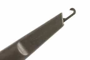
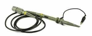
Oscilloscope probes normally comprise a BNC connector, the coaxial cable (typically around a metre in length) and what may be termed the probe itself. This comprises a mechanical clip arrangement so that the probe can be attached to the appropriate test point, and an earth or ground clip to be attached to the appropriate ground point on the circuit under test.
Care should be taken when using oscilloscope probes as they can break. Although they are robustly manufactured, any electronics laboratory will consider oscilloscope probes almost as "life'd" items that can be disposed of after a while when they are broken. Unfortunately the fact that they are clipped on to leads of equipment puts a tremendous strain on the mechanical clip arrangement. This is ultimately the part which breaks.
X1 and X10 oscilloscope probes
There are two main types of passive voltage scope probes. They are normally designated X1 and X10, although 1X and 10X are sometimes seen. The designation refers to the factor by which the impedance of the scope itelf is multiplied by the probe.
The X1 probes are suitable for many low frequency applications. They offer the same input impedance of the oscilloscope which is normally 1 MΩ. However for applications where better accuracy is needed and as frequencies start to rise, other test probes are needed.
To enable better accuracy to be achieved higher levels of impedance are required. To achieve this attenuators are built into the end of the probe that connects with the circuit under test. The most common type of probe with a built in attenuator gives an attenuation of ten, and it is known as a X10 oscilloscope probe. The attenuation enables the impedance presented to the circuit under test to be increased by a factor of ten, and this enables more accurate measurements to be made.
As the X10 probe attenuates the signal by a factor of ten, the signal entering the scope itself will be reduced. This has to be taken into account. Some oscilloscopes automatically adjust the scales according to the probe present, although not all are able to do this. It is worth checking before making a reading.
The 10X scope probe uses a series resistor (9 M Ohms) to provide a 10 : 1 attenuation when it is used with the 1 M Ohm input impedance of the scope itself. A 1 M Ohm impedance is the standard impedance used for oscilloscope inputs and therefore this enables scope probes to be interchanged between oscilloscopes of different manufacturers.

The scope probe circuit shown is a typical one that might be seen - other variants with the variable compensation capacitor at the tip are just as common.
In addition to the X1 and X10 scope probes, X100 probes are also available. These oscilloscope probes tend to be used where very low levels of circuit loading are required, and where the high frequencies are present. The difficulty using the is the fact that the signal is attenuated by a factor of 100.
X10 oscilloscope probe compensation
The X10 scope probe is effectively an attenuator and this enables it to load the circuit under test far less. It does this by decreasing he resistive and capacitive loading on the circuit. It also has a much higher bandwidth than a traditional X1 scope probe.
The x10 scope probe achieve a better high frequency response than a normal X1 probe for a variety of reasons. It does this by decreasing the resistive and capacitive loading on the The X10 probe can often be adjusted, or compensated, to improve the frequency response.
For many scope probes there is a single adjustment to provide the probe compensation, although there can be two on some probes, one for the LF compensation and the other for the HF compensation.
Probes that have only one adjustment, it is the LF compensation that is adjusted, sometimes the HF compensation may be adjusted in the factory.
To achieve the correct compensation the probe is connected to a square wave generator in the scope and the compensation trimmer is adjusted for the required response - a square wave.

As can be seen, the adjustment is quite obvious and it is quick and easy to undertake. It should be done each time the probe is moved from one input to another, or one scope to another. It does not hurt to check it from time to time, even if it remains on the same input. As in most laboratories, things get borrowed and a different probe may be returned, etc . .
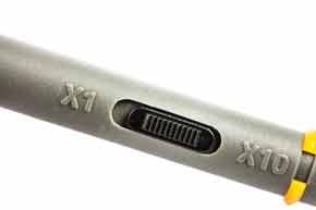
A note of caution: many oscilloscope probes include a X1/X10 switch. This is convenient, but it must be understood that the resistive and capacitive load on the circuit increase significantly in the X1 position. It should also be remembered that the compensation capacitor has no effect when used in this position.
As an example of the type of loading levels presented, a typical scope probe may present a load resistance of 10MΩ along with a load capacitance of 15pF to the circuit in the X10 position. For the X1 position the probe may have a capacitance of possibly 50pF plus the scope input capacitance. This may end up being of the order of 70 to 80pF.
Other types of probe
Apart from the standard 1X and 10X voltage probes a number of other types of scope probe are available.
- Current probes: It is sometimes necessary to measure current waveforms on an oscilloscope. This can be achieved using a current probe. This has a probe that clips around the wire and enables the current to be sensed. Sometimes using the maths functions on a scope along with a voltage measurement on another channel it is possible to measure power, as well as looking at the phase differences.
Read more about . . . . Oscilloscope Current Probes.
- Active probes: As frequencies rise, the standard passive probes become less effective. The effect of the capacitance rises and the bandwidth is limited. To overcome these difficulties active probes can be used. They have an amplifier right at the tip of the probe enabling measurements with very low levels of capacitance to be made. Frequencies of several GHz are achievable using active scope probes.
- Differential scope probes: In some instances it may be necessary to measure differential signals. Low level audio, disk drive signals and many more instances use differential signals and these need to be measured as such. One way of achieving this is to probe both lines of the differential signal using one probe each line as if there were two single ended signals, and then using the oscilloscope to add then differentially (i.e. subtract one from the other) to provide the difference.
Using two scope probes in this way can give rise to a number of problems. The main one is that single ended measurements of this nature do not give the required rejection of any common mode signals (i.e. Common Mode Rejection Ratio, CMMR) and additional noise is likely to be present. There may be a different cable length on each probe that may lead to a time differences and a slight skewing between the signals.
To overcome this a differential probe may be used. This uses a differential amplifier at the probing point to provide the required differential signal that is then passed along the scope probe lead to the oscilloscope itself. This approach provides a far higher level of performance. - High voltage probes: Most standard oscilloscope voltage probes like the X1 or X10 are only specified for operation up to voltages of a few hundred volts at most. For operation higher than this a proper high voltage probe with specially insulated probe is required. It also will step down the voltage for the input to the scope so that the test instrument is not damaged by the high voltage. Often voltage probes may be X50 or X100.
Summary
Oscilloscope probes are an essential addition to any oscilloscope. In most case 10X passive scope probes may be used, but other types of test probe need to be considered dependent upon the applications envisaged.
More Test Topics:
Data network analyzer
Digital Multimeter
Frequency counter
Oscilloscope
Signal generators
Spectrum analyzer
LCR meter
Dip meter, GDO
Logic analyzer
RF power meter
RF signal generator
Logic probe
PAT testing & testers
Time domain reflectometer
Vector network analyzer
PXI
GPIB
Boundary scan / JTAG
Data acquisition
Return to Test menu . . .

