
What is a Spectrum Analyzer: RF spectrum analyzer
RF spectrum analyzers are test instruments used to look at signals in the frequency domain, i.e. a plot of signal strength against frequency.
Spectrum Analyzer Tutorial Includes:
What is a spectrum analyzer
Spectrum analyzer types and technologies
Superheterodyne / sweep spectrum analyzer
FFT spectrum analyzer
Realtime spectrum analyzer
USB spectrum analyzer
Spectrum analyzer tracking generator
Specifications
Spectrum analyzer operation
Noise figure measurements
Phase noise measurements
Pulsed signal spectrum analysis
Spectrum analyzers are found in many laboratories and other areas where test instruments are needed to test and verify radio frequency RF performance.
Spectrum analyzers are widely used test instruments for applications where RF testing is needed: in RF design, general electronic circuit design, testing; electronics manufacturing; base service and repair, and increasingly in field installation and service.

In these applications, RF spectrum analyzers are able to provide an effective insight into the RF performance of a circuit, module or system.
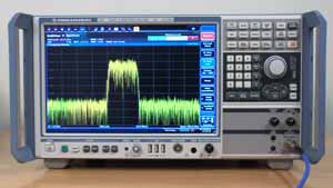
As the name spectrum analyzer indicates, this type of test equipment provides information about the spectrum of a signal. As signals on different frequencies can be seen, it enables spurious signals as well as the spectrum of today's complex waveforms to be displayed to investigate whether they fall within the required limits on different frequencies.
With the increasing use of wireless communications, spectrum analyzers form an essential part of the RF design tool box and are seen increasingly in many areas of electronics circuit design.
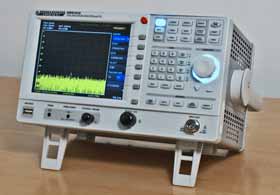
Although spectrum analysers have traditionally been items of stand-alone bench test equipment, rack mount PXI, VXI or similar analysers are available along with USB spectrum analyzers. Even the bench top test instruments have the capability to link to computers so that they can be controlled by them and also their results analysed in greater detail.
What is a spectrum analyser?
The most commonly used item of test equipment that displays waveforms is the oscilloscope. This test instrument displays signals in what is termed the time domain, i.e. amplitude against time. The oscilloscope is one of the core test instruments for any RF design or test laboratory and enables many waveforms to be displayed and the performance of circuits. modules and equipment to be analyzed.
The oscilloscope displays the amplitude of waveforms on the vertical axis against time on the horizontal axis - signals are displayed in the time domain.
Whilst this is vey useful, when testing radio frequency circuits and systems in particular, it is useful to be able to see the spectrum of a signal - it is possible to look at aspects like the location of spurious signals, the width of a signal that has modulation on it, whether noise is being generated and much more.
When looking at the spectrum of a signal, the amplitude of signals is displayed in the vertical axis and frequency in the horizontal axis - signals are displayed in the frequency domain.
By looking at the amplitudes of signals at different frequencies it is possible to measure the amplitudes of these signals, find what signals are present and the like.

In this way it is possible to measure the frequencies of signals, and also check their levels. With many modern day wireless communications signals occupying wide bandwidths, it is possible to measure the signal bandwidths.
Accordingly, the spectrum analyzer is a particularly important item of test equipment for anyone undertaking the test and measurement of circuits and systems involving radio frequency or RF signals. In addition to this, spectrum analyzers may also be used for a variety of other applications including audio analysis and the like.
RF design is becoming more important with the growing use of wireless communications systems with everything from Wi-Fi to mobile phones and remote wireless sensors on the Internet of Things, as well as radar, traditional radio communications and a host of other applications.
Spectrum analysers normally use a linear scale for the frequency on the horizontal or x-axis, but they normally use a logarithmic scale for the amplitude on the vertical or y-axis. By using a logarithmic or decibel scale for the amplitude scale, it is possible to see signals with large differences in amplitude.
Signals being viewed on a spectrum analyzer may differ by 60dB, 70 dB or more. Using a logarithmic scale is the only way to see these signals on the same screen. For some applications it may be necessary to use a linear amplitude scale, and often there is a switch to accomplish this.
Modern spectrum analyzers have a high degree of capability. As most use digital techniques, not only is the signal processing accomplished using digital signal processing using Fast Fourier Analysis, FFT, but also the front panel controls and display are controlled using a control processor. This enables the spectrum analyzer to incorporate a host of capabilities and include a good number of automated routines.
The display can normally determine the peak signal, displaying its frequency and power level, or the it can determine the value of the signal at a particular point, or the value of a second peak, etc. These and many functions are common place in todays test instruments.
Uses for Spectrum analyzers
Todays electronic circuit design laboratories will use very many test instruments. Everything from simple digital multimeters to oscilloscopes, signal generators and much more.
Spectrum analyzers are particularly used in electronics laboratories associated with RF design and test.
In these areas they can provide a view of a signal in a way that no other form of test instrument is able. This gives insights into the operation fo the radio frequency aspects of the circuit.
The spectrum analyzer can be used for a number of tasks:
- Looking at the frequency spectrum of a signal to see items like the following:
- The overall spectrum of a modulated signal to see whether it is wide enough or too narrow, etc. If it is too wide then it could cause interference to users in adjacent channels.
- To investigate whether any spurious or unwanted signals are present. These signals could cause interference to users on other frequencies is signals are transmitted.
- To find out whether a signal is on the right frequency, and not in another band for example.
- To investigate general problems with a signal. Often it can just help looking at a signal to see what a problem is. With RF signals a spectrum analyzer can prove to be the eyes for the person investigating the problem.
- Sometimes spectrum analyzers can be used to measure power, although power meters may be more applicable in some circumstances.
- Sometimes spectrum analyzers can be used to measure frequency, although frequency counters may be more applicable in some circumstances.
- Spectrum analysers can also be used to measure the phase noise on a signal. This can be achieved provided that the pose noise on the spectrum analyzer local oscillator is typically 10dB better than that of the oscillator under test. These test instruments are one of the best ways to measure phase noise provided the spectrum analyzer local oscillator has a sufficiently low level of phase noise.
- Another application for these test instruments is that of measuring the noise figure of an item. Although the test method does involve a number of stages, it can be undertaken relatively easily.
- Spectrum analysers are often used when undertaking EMI & EMI (electromagnetic interference and electromagnetic compatibility) measurements. The analyzer can be used to locate the frequency and nature of the signal that may be causing an issue.
Although the RF spectrum analyzer can be used for many radio frequency tests, the table below gives a summary of the different types of test instruments used for RF testing and their typical applications.
| Where to use different types of RF Test Equipment |
|||
|---|---|---|---|
| TestEquipment Type | Frequency measurement | Intensity / amplitude measurement | Application |
| Power meter | N | Y | RF power meters provide accurate total power measurements, but they are unable to provide any information about the signal spectrum. |
| Frequency counter | Y | N | A frequency counter us used to provide very accurate measurements of the dominant frequency within a signal |
| RF Spectrum analyser | Y | Y | Used primarily to display the spectrum of a radio frequency signal. Can also be used to make power and frequency measurements, although not as accurately as dedicated instruments |
| RF vector network analyser | Y | Y | Vector network analyzers, VNAs measure the properties of RF devices. They look at the various ports on the device and provide information about the impedance of the ports and transmission through the device. |
Spectrum analyzer key topics
There are several key topics that are associated with RF spectrum analyzers and their use.
Spectrum analyzer types: There are several different types of spectrum analyzer that can be bought and used. Each type has its own characteristics: performance and cost can be balanced to give the best option for any application.
Older types are normally based around the superheterodyne principle, sweeping the receiver across a band of frequencies and noting the output. More modern spectrum analysers use fast Fourier transforms, FFTs, converting the signal from an analogue to a digital format and then using Fourier analysis to monitor the sign.
There are also real time spectrum analysers. These are based upon the same concept as FFT spectrum analyzers, but these test instruments use time overlapping samples to ensure that no transients are lost. Although more complicated internally, because they need to be able to accommodate very fast and overlapping sampling, they ensure that all signals can be seen. They are often essential for resolving some of the issues with the very complicated equipment that is being produced today for the various forms of wireless communication: 5G; Wi-Fi, etc . .
There are also variations in the format of the test instruments as well. Standard box instruments are widely used, and not only do they offer manual control, but they also provide provision for remote operation via a number of different interfaces often including Ethernet, USB and GPIB.
There are also options for rack mounted spectrum analyzers. VXI was an early rack system, but today PXI is more widely used. Based on the PCI system, PXI has been adapted for instrumentation use. A controller or interface sits in one slot, leaving the remaining ones for test instruments. The controller may control the system, or more usually be linked to a computer. This type of approach is ideal for computer control of a collection of test instruments needed for testing a system under computer control.
Another approach is to have a USB spectrum analyzer. These USB spectrum analyzers have the main functionality of the analyser in a small box, but this is connected to a PC via a USB cable so that it can use display, control and control processing and often the power supply from the PC to reduce the cost whilst often maintaining the performance levels. Some USB spectrum analyzers are able to offer a very high level of performance at quite a reasonable cost.
Read more about . . . . Spectrum analyzer types and technologies.
Spectrum analyzer specifications: When choosing an RF spectrum analyzer it is necessary to understand the specifications and what they mean. There are many different specifications associated with the performance of a spectrum analyzer, and it is necessary to understand what they mean and how they reflect into the actual performance of the test instrument.
There are many specifications to be considered when selecting a spectrum analyzer. The various specifications cover a variety of aspects of their performance. The frequency coverage: top and bottom frequencies are obviously important, together wit the frequency and amplitude accuracy. Phase noise is another key issue because many these test instruments often need to be able to measure the phase noise performance of other devices and to achieve this their performance needs to be better than that of the item under test.
Many other aspects of the performance, including the facilities available need to be taken into account when making and selections.
Read more about . . . . Spectrum analyzer specifications.
How to use a spectrum analyzer: A spectrum analyzer is a complicated type of test instrument. This summary with a video gives a really helpful guide on their use.
In order to get the best from any spectrum analyzer, it is necessary to understand the operation of the various controls. For anyone using this type of test equipment fort he first time, it can take a little while to get to grips with the different controls, but soon they become second nature.
Read more about . . . . How to use a spectrum analyzer.
The RF spectrum analyzer is an essential item of test equipment for any radio frequency engineer whether used for RF design, general electronic circuit design, electronics manufacturing, service, repair, and general RF test.
Although spectrum analyzers are normally expensive test instruments to buy, they can occasionally be picked up on the second hand market and this would make them accessible to enthusiastic RF experimenters and radio hams.
In addition to this, some USB spectrum analysers offer very high levels of value as they use elements of the PC for display, and entry of the controls. Typically most of the signal analysis is undertaken by an FPGA in the USB spectrum analyzer itself and this means that high levels of functionality and performance can be obtained at a much more reasonable cost.
Spectrum analyzers can also be obtained in a rack mounting format. VXI and PXI spectrum analyzers are available, if these rack systems are being used.
The spectrum analyzer is an essential item of test equipment used in RF test and RF design laboratories where they are used extensively, but they are not normally found outside these environments, although audio analysers are used for some specific tests.
More Test Topics:
Data network analyzer
Digital Multimeter
Frequency counter
Oscilloscope
Signal generators
Spectrum analyzer
LCR meter
Dip meter, GDO
Logic analyzer
RF power meter
RF signal generator
Logic probe
PAT testing & testers
Time domain reflectometer
Vector network analyzer
PXI
GPIB
Boundary scan / JTAG
Data acquisition
Return to Test menu . . .

