
Superhet Radio Receiver: What it is & How it Works
Understand what the superhet or superheterodyne radio is, how it works, where it is used, its advantages & disadvantages and how it became one of the most successful forms of radio receiver.
Superhet Radio Tutorial Includes:
Superhet radio
Superhet theory
Image response
Block diagram / overall receiver
Design evolution
Double & multi-conversion superhet
Specifications
See also: Radio types
One of the most common forms of radio receiver is the superhet or superheterodyne radio receiver. Virtually all broadcast radio receivers, as well as televisions, short wave receivers and commercial radios have used the superheterodyne principle as the basis of their operation.
Invented in 1918 to overcome the issues of lack of selectivity, superhet designs have been at the centre of radio communications technology for nearly 100 years, and only recently are other topologies taking over.
Video: Understanding the Superhet Radio
Despite this the superheterodyne radio is still used in many applications and the RF design techniques used are still applicable in many radio communications applications.
The superheterodyne radio receiver, although the RF circuit design is more complicated than some other forms of radio set, offers many advantages in terms of performance, particularly its selectivity.
The superhet radio works by using a variable frequency local oscillator and feeding the incoming signals and the local oscillator into an RF mixer to convert the signals to a fixed frequency intermediate frequency.
By having a fixed frequency amplification and filtering stages it enables the radio to remove unwanted signals more effectively than other forms like the TRF (Tuned Radio Frequency) sets or even regenerative radios that were used particularly in the early days of radio.
Superhet radio applications & usage
The superhet radio used to be the undoubted radio receiver technique of choice. It was almost universally used. However, nowadays with software defined radios taking over the superhet is used less widely.
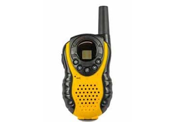
The superhet was used in every form of radio from domestic broadcast radios to walkie talkies, television sets, through to hi-fi tuners and professional communications radios, satellite base stations and much more.
Superhet radio history
The story of the development and RF circuit design technology of the superheterodyne radio receiver can be traced back to the earliest days of radio. Reginald Fessenden noticed that signals on adjacent wavelengths created a beat note together. Later in during the First World War the benefits of using radio technology started to be realised and the need to radios that were selective and provided sufficient gain and sensitivity were needed.
Several engineers tackled the problem: Lucien Levy in France, Walter Schottky in Germany and finally the man to whom the superheterodyne technique is credited, Edwin Armstrong who built the first working superhet radio.
Note on the Superheterodyne Radio History:
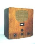
The superheterodyne radio was invented in an age when radio technology was very basic and radio receiver performance lacked what we would take for granted today. The superhet radio, or to give it is full name, the supersonic heterodyne wireless receiver represented a major step forwards in performance, but initially it was not widely used, partly because it was invented at the end of the First World War, and secondly because it used a lot of valves / tubes and these were very expensive at this time.
Read more about the fascinating story of the invention of the superheterodyne radio receiver.
Superheterodyne receiver key technologies & how it works
As mentioned above, superheterodyne or superhet radio works by using a variable frequency local oscillator and an RF mixer. The incoming signals and the local oscillator signals enter the RF mixer and thee incoming signal is converted down to a fixed frequency intermediate frequency stage that provides the majority of the gain and adjacent channel selectivity, i.e rejecting the unwanted off-channel signals.
By having a fixed frequency amplification and filtering stages the radio is able to remove unwanted signals more effectively because high performance filters are able to provide much better performance than variable frequency ones.
To achieve the overall superhet radio topology, there are several techniques and technologies that are involved within the receiver.
Overall theory: The basic concept and RF design behind the superheterodyne radio involves the process of mixing. This enables signals to be translated from one frequency to another. The input frequency is often referred to as the RF input, whilst the locally generated oscillator signal is referred to as the local oscillator, and the output frequency is called the intermediate frequency as it is between the RF and the audio frequencies.

Block diagram of a basic superheterodyne receiver Within a mixer the instantaneous amplitude of the two input signals (f1 and f2) is multiplied and this results in signals at the output of frequencies of (f1 + f2) and (f1 - f2). This enables an incoming frequency to be translated down to a fixed frequency where it can be effectively filtered. Varying the frequency of the local oscillator enables the receiver to be tuned to different frequencies.
Read more about . . . . superheterodyne receiver theory & principles.
Image response: One of the key issues within the superhet radio is that of the image response. It is possible for signals on two different frequencies to enter the intermediate frequency stages. RF tuning removes one and accepts the other.
When image signals are present they can cause unwanted interference, masking out wanted signals if both appear at the same place within the intermediate frequency section. Often in low cost radios, harmonics of the local oscillator can track at different frequencies giving rise to varying heterodynes as the receiver is tuned. Good image rejection is one of the keys to a high performance radio receiver.
Read more about . . . . image response.
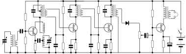
Block diagram: The overall superhet receiver block diagram shows the basic blocks that can be used within the receiver. The basic block diagram of the superheterodyne receiver enables the overall operation of the radio to be understood.
In more sophisticated radios, there will be additional blocks added to the basic block diagram. There may be additional blocks for additional demodulators, or there can be additional circuit blocks within the local oscillator, dependent upon the level of details required. In addition to this some superheterodyne radios may have two or more conversions to provide enhanced performance in a variety of respects.Read more about . . . . superheterodyne receiver block diagram.
Double conversion: To improve elements of the performance including the image rejection, two or even three conversions may be used.
Superhet receiver advantages
The superheterodyne radio offers a number of advantages over other forms of radio.
Its flexibility and capabilities has meant that it was adopted for very many uses from broadcast reception, uses as a test receiver for EMI / EMC testing, two way radio communications, reception for scientific applications, satellite signal reception and many others.
As a result of its advantages the superheterodyne receiver has remained as one of the foremost techniques used in radio technology.
Although today, other techniques are coming to the fore increasingly, nevertheless the superhet receiver is still very widely used in view of the benefits it is able to offer.
Some of the key advantages offered by the superhet receiver include:
Good adjacent channel selectivity: One of the major advantages of the superheterodyne receiver is the close in or adjacent channel selectivity it offers. Using fixed frequency filters it is able to provide excellent adjacent channel rejection.
By using a fixed frequency intermediate stage, fixed frequency filters can be used. As they are fixed in frequency, their performance is the same whatever the frequency of the incoming signal. Not only is the RF circuit design for fixed frequency filters much easier, but it also enables constant performance. It also enables very high performance filters to be developed in a way that would not be possible if they were variable in frequency.
Able to receive multiple modes: In view of its topology this the superhet radio is able to incorporate a variety of different types of demodulator which can be easily selected according to the requirements.
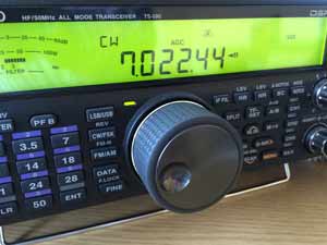
Adding the capablity for a new form of modulation simply means that another demodulator is added to the end of the intermediate frequency amplifier. Commonly used modes include AM, FM, SSB, Morse / CW, and various data modes using forms of phase shift keying or quadrature amplitude modulation. During the RF circuit design for the receiver, a new form of modulator can be added, and they can be switched or selected as required.
Able to receive very high frequency signals: The fact that the superheterodyne receiver uses mixing technology means that the majority of the receiver processing is done at lower frequencies lending itself to the possible reception of exceedingly high frequency signals.
If signals at VHF, UHF or wherever are needed, then it is possible to convert the signal down to the required intermediate frequency in several stages. The RF circuit design can accommodate the addition of further conversions and accordingly the superheterodyne radio receiver can be used for many two way radio communication applications at all frequencies as well as broadcast receptions, etc.
Good sensitivity: When compared to some other forms of radio receiver, the superheterodyne format enabled good levels of sensitivity to be achieved. Although these days, other formats provide equivalent levels of sensitivity, in the early days of wireless communications, the superhet was way ahead of others like the TRF, etc.
These and many other advantages mean that the superheterodyne receiver has been in use since the early days of radio and is likely to remain so for many years to come.
More Essential Radio Topics:
Radio Signals
Modulation types & techniques
Amplitude modulation
Frequency modulation
OFDM
RF mixing
Phase locked loops
Frequency synthesizers
Passive intermodulation
RF attenuators
RF filters
RF circulator
Radio receiver types
Superhet radio
Receiver selectivity
Receiver sensitivity
Receiver strong signal handling
Receiver dynamic range
Return to Radio topics menu . . .

