What is Capacitance: basic concepts
Capacitance is one of the basic concepts behind electronics, and it is widely used, as seen by the number of capacitors that are used in electronic circuits
Capacitance Tutorial Includes:
Capacitance
Capacitor formulas
Capacitive reactance
Parallel & series capacitors
Dielectric constant & relative permittivity
Dissipation factor, loss tangent, ESR
Capacitor conversion chart
Resistance, capacitance and inductance are three basic parameters associated with electrical and electronic circuits.
Unlike the other two, capacitance is associated with the storage of electrical charge and the attributes are used in electronic components called capacitors and in turn these are used in many electrical circuits and virtually every electronic circuit design.
The effects of capacitance can be used in a variety of ways in circuits ranging from electrical motors to electronic circuit designs like power supplies, audio circuits, RF circuits, logic and digital circuits and very many more.
In view of this, capacitance is a particularly important parameter which is used in many areas.
What is capacitance
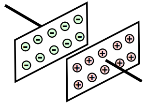
When looking at capacitance, it is first necessary to look at exactly what it is. Capacitance is effectively the ability to store charge. In its simplest form a capacitor consists of two parallel plates. It is found that when a battery or any other voltage source is connected to the two plates as shown a current flows for a short time and one plate receives an excess of electrons, while the other has too few.
In this way one plate, the one with the excess of electrons becomes negatively charge, while the other becomes positively charged.
If the battery is removed the capacitor will retain its charge. However if a resistor is placed across the plates, a current will flow until the capacitor becomes discharged.
Accordingly it is possible to define what capacitance is:
Capacitance definition:
Capacitance is the ability of a component or circuit to collect and store energy in the form of an electrical charge. It is the amount of electric charge stored on a conductor for a stated difference in electric potential.
The larger the plates, the more charge can be stored, and also the closer they are together, the more charge they store. The charge storage is also dependent upon the material between the two plates as well.
Units or capacitance
It is necessary to be able to define the "size" of a capacitor. The capacitance of a capacitor is a measure of its ability to store charge, and the basic unit of capacitance is the Farad, named after Michael Faraday.
It is worth defining the Farad which is the basic unit of capacitance.
Capacitance: Farad definition:
A capacitor has a capacitance of one Farad when a potential difference of one volt will charge it with one coulomb of electricity (i.e. one Amp for one second).
A capacitor with a capacitance of one Farad is too large for most electronics applications, and components with much smaller values of capacitance are normally used. Three prefixes (multipliers) are used, µ (micro), n (nano) and p (pico):
| Capacitance Units Prefixes and Multipliers | ||
|---|---|---|
| Prefix | Multiplier | Terminology |
| µ | 10-6 (millionth) | 1000000µF = 1F |
| n | 10-9 (thousand-millionth) | 1000nF = 1µF |
| p | 10-12 (million-millionth) | 1000pF = 1nF |
Electric fields and dielectrics
As there is a potential across the plates of a capacitor, there is an associate electric field present. With parallel plates, the electric field lines are generally parallel to each other and at right angles to the plates.

Capacitors require some form of insulator between the two plates, otherwise the charge could not remain on the plates, it would dissipate through the medium between the two plates.
Whilst air is a good insulator, often the capacitor plates need to be kept apart by some form of rigid insulator.

The material between the two plates is called the dielectric. This not only acts as an insulator, but it also determines many of the other properties. A measure known as the dielectric constant affects the level of capacitance achievable for a given capacitor plate size and spacing.
High levels of relative permittivity / dielectric constant can increase the capacitance many times.
The topic of relative permittivity and dielectric constant, etc, is a topic in its own right, and although easy to comprehend, possibly needs to be looked at separately.
Capacitor charging and discharging
It is also possible to look at the voltage across the capacitor as well as looking at the charge. After all it is easier to measure the voltage on it using a simple meter. When the capacitor is discharged there is no voltage across it. Similarly, one it is fully charged no current is flowing from the voltage source and therefore it has the same voltage across it as the source.
In an ideal circuit with no stray resistance or inductance, when a voltage is applied to a capacitor, it would instantly charge up and the voltage across it would be the same as that of the source of the electric potential.
In reality there will always be some resistance in the circuit, and therefore the capacitor will be connected to the voltage source through a resistor. This means that it will take a finite time for the capacitor to charge up, and the rise in voltage does not take place instantly.
It is found that the rate at which the voltage rises is much faster at first than after it has been charging for some while. Eventually it reaches a point when it is virtually fully charged and almost no current flows.
In theory the capacitor never becomes fully charged as the curve is asymptotic. However in reality it reaches a point where it can be considered to be fully charged or discharged and no current flows.
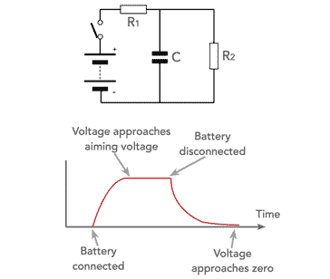
Similarly the capacitor will always discharge through a resistance. As the charge on the capacitor falls, so the voltage across the plates is reduced. This means that the current will be reduced, and in turn the rate at which the charge is reduced falls.
This means that the voltage across the capacitor falls in an exponential fashion, gradually approaching zero.
The rate at which the voltage rises or decays is dependent upon the resistance in the circuit. The greater the resistance the smaller the amount of charge which is transferred and the longer it takes for the capacitor to charge or discharge.
Application of alternating waveform to a capacitor
So far the case when a battery has been connected to charge the capacitor and disconnected and a resistor applied to charge it up have been considered. If an alternating waveform, which by its nature is continually changing is applied to the capacitor, then it will be in a continual state of charging and discharging.
For this to happen a current must be flowing in the circuit. In this way a capacitor will allow an alternating current to flow, but it will block a direct current. As such capacitors are used for coupling an AC signal between two circuits which are at different steady state potentials.

Note: the current leads the voltage waveform by 90°.
It is found that when the sine-wave is first applied first applied, the rate of change of the voltage is at its greatest and this means that the charge is increasing at its fastest rate and hence the current flowing into the capacitor will be at its greatest. In other words the current is at its maximum.
As the voltage on the capacitor increases, the rate of change of voltage decreases and as a result the increase in charge and hence the current falls. Eventually the peak of the voltage sine-eave is reached where there is no change in voltage and accordingly the current at this point is zero.
After the voltage peak, the voltage starts to decreases, and accordingly the level of charge falls and this means that current flows out of the capacitor from this point.
The remainder of the waveform follows in a similar fashion. As a result it can be seen that the voltage and current are not in phase with each other. The current lags the voltage by a quarter of a cycle, i.e. 90°.
It is possible to express the current and voltage relationship for a perfect capacitor as:
Real capacitors
Capacitors are the electronic components that provide the capacitance required in electrical and electronic circuits.
Capacitors come in a wide variety of forms, each with its own properties. The physical capacitors may be either surface mount or the traditional leaded varieties as well as having different form factors and electrical performance properties.
Note on the Types of Capacitor:
There are many different types of capacitor that are available. Although capacitance is a universal measure, different capacitors have different characteristics in terms of elements like maximum current capability, frequency response, size, voltage, stability, tolerance and the like. To accommodate these parameters some capacitor types are better than others in some applications,
Read more about Capacitor Types.

Selecting the right capacitor is not only a matter of choosing the right level of capacitance, but also many other aspects including the dielectric, size, levels of equivalent series resistance and many more items.
In view of all these requirements, there is a very wide selection of these electronic components available for use in electrical and electronic circuit designs, etc.
Capacitance is one of the main parameters associated with electrical and electronic science. Capacitance equations and calculations are used everyday in electronic circuit design and many other areas, and capacitance is not a measure that is only associated with capacitors, there can be levels of capacitance in many other electronic components including resistors, inductors, wires, printed circuit boards and many other items.
More Basic Electronics Concepts & Tutorials:
Voltage
Current
Power
Resistance
Capacitance
Inductance
Transformers
Decibel, dB
Kirchoff's Laws
Q, quality factor
RF noise
Waveforms
Return to Basic Electronics Concepts menu . . .