
Over-voltage Protection for Power Supplies
Power supply over-voltage protection is really useful - some PSU failures can put damaging large voltages on the equipment. Over-voltage protection prevents this happening on both linear regulators and switch mode power supplies.
Power Supply Circuits Primer & Tutorial Includes:
Power supply circuits overview
Linear power supply
Switch mode power supply
Capacitor smoothing
AC rectifier circuits
Voltage regulator circuits
Zener voltage regulator circuit
Over-voltage protection
PSU specs
Digital Power
Power management bus: PMbus
Uninterruptible power supply
Although modern power supplies are now very reliable, there is always a small but real chance that they can fail.
Power supplies can fail in many ways and one particularly worrying possibility is that the series pass element of a linear power supply, i.e. main pass transistor or FET may fail in such a way that it goes short circuit.
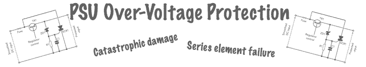
If this happens a very large voltage often referred to as an over-voltage could appear on the circuitry that is being powered causing catastrophic damage to the whole equipment.
By adding a little extra protection circuitry in the electronic circuit design stage in the form of over-voltage protection, it is possible to protect against this unlikely but catastrophic possibility.
Most power supplies designed for very reliable operation of high value equipment will incorporate some form of over-voltage protection in the electronic circuit design to ensure that any power supply failure does not result in damage to the equipment being powered. This applies to both linear power supplies and also to switch mode power supplies.
Some power supplies may not incorporate over-voltage protection and these should not be used for powering expensive equipment - it is possible to do a little electronic circuit design and to develop a small over-voltage protection circuit and add this on as an extra item.
Over-voltage protection basics
There are many ways in which a power supply can fail. However to understand a little more about over-voltage protection and the electronic circuit design issues it is easy to take a simple example of a linear voltage regulator using a very simple Zener diode and a series pass transistor.

Although more complicated supplies give better performance, they also rely on a series transistor to pass the output current. The main difference is the way in which the regulator voltage is applied to the base of the transistor.
Typically the input voltage is such that several volts are dropped across the series voltage regulator element. This enables the series pass transistor to regulate the output voltage adequately.
Often the voltage dropped across the series pass transistor is relatively high - for a 12 volts supply, the input may be 18 volts of even more to give the required regulation and ripple rejection, etc.
This means that there can be a significant level of heat dissipated in the voltage regulator element and combined with any transient spikes that could appear at the input, this means there is always a possibility of failure.
The transistor series pass device would more usually fail in an open circuit condition, but under some circumstances, the transistor may develop a short circuit between the collector and emitter. For a FET, the equivalent would be a short circuit between the drain and source.
In the event of a short circuit between the collector and emitter, or drain and source an FET, the full unregulated input voltage would appear in the output of the voltage regulator.
If the full voltage appeared on the output, then it could damage many of the ICs that are in the circuit being supplied. In this case the circuit could well be beyond economic repair.
The way in which switching regulators operate is very different, but there are circumstances in which the full output could appear on the output of the power supply.
For both linear regulated power supplies and switch mode power supplies, some form of over-voltage protection is always advisable.
Types of over-voltage protection
As with many electronic techniques there are several ways of implementing a particular capability. This is true for over-voltage protection.
There are several different techniques that can be used, each with its own characteristics. Performance, cost, complexity and mode of operation all need to be weighed up when determining which method to use during the electronic circuit design stage.
SCR Crowbar over voltage protection
As the name implies the crowbar circuit places a short circuit across the output of the power supply if an over-voltage condition is experienced. This shorts the output line to ground.
Typically thyristors, i.e. SCRs are used for this as they can switch large currents and remain on until any charge has dispersed. The thyristor can be linked back to a fuse which blows and isolates the regulator from having any further voltage placed upon it.

In this electronic circuit design, the Zener diode is chosen so that its voltage is above the normal operating voltage of the output, but below the voltage where damage would occur.
In this state, no current flows through the Zener diode because its breakdown voltage has not been reached and no current flows into the gate of the thyristor and it remains off. The power supply will operate normally.
If the series pass transistor in the power supply fails, the voltage will start to rise - the decoupling in the unit will ensure it does not rise instantly.
As it rises, it will rise above the point where the Zener diode starts to conduct and current will flow into the gate of the thyristor causing it to trigger.
When the thyristor triggers, it will short the output of the power supply to ground, preventing damage to the circuitry it powers.
This short circuit can also be used to blow a fuse or other element, taking the power off the voltage regulator and isolating the unit from further damage.
Often some decoupling in the form of a small capacitor is placed from the gate of the thyristor to ground to prevent sharp transients or RF from the unit being power from getting on to the gate connection and causing a spurious trigger.
However this capacitor should not be made too large as it may slow the circuit firing in a real case of failure and the protection may be in place too slowly.
Note on Thyristor Crowbar Overvoltage Protection:
The Thyristor or SCR, Silicon Controlled Rectifier can be used to provide overvoltage protection in a power supply circuit. By detecting the high voltage, the circuit can fire the thyristor to place a short circuit or crowbar across the voltage rail to ensure it does not rise to high in voltage.
Read more about Thyristor Crowbar Overvoltage Protection Circuit.
Voltage clamping over voltage protection
Another very simple form of over-voltage protection uses an approach called voltage clamping. In its simplest form it can be provided by using a Zener diode placed across the output of the regulated power supply.
With the Zener diode voltage chosen to be slightly above the maximum rail voltage, under normal conditions it will not conduct. If the voltage rises too high, then it will start to conduct, clamping the voltage at a value slightly above the rail voltage.
If a higher current capability is needed for the regulated power supply then a Zener diode with a transistor buffer can be used. This will increase the current capability over the simple Zener diode circuit, by a factor equal to the current gain of the transistor. As a power transistor is required for this circuit, the likely current gain levels will be low - possibly 20 - 50.

(a) - simple Zener diode, (b) - higher current with transistor buffer
Voltage limiting
When over-voltage protection is required for switch mode power supplies, SMPS the clamp and crowbar techniques are less widely used because of the power dissipation requirements and the possible size and cost of the components.
Fortunately most switch mode regulators fail in a low voltage condition. However it is often prudent to put in place voltage limiting capabilities in case of over-voltage conditions.
Often this can be achieved by sensing the over-voltage condition and shutting down the converter. This is particularly applicable in the case of DC-DC converters. When implementing this, it is necessary to incorporate a sense loop that is outside the main IC regulator - many switch mode regulators and DC-DC converters use a chip to achieve the majority of the circuit.
It is very important to use an external sense loop because if the switch mode regulator chip is damaged causing the over-voltage condition, the sense mechanism may also be damaged.
Obviously this form of over-voltage protection requires circuits that are specific to the particular circuit and switch mode power supply chips used.
All three techniques are used and can provide effective power supply over-voltage protection. Each has its own advantages and disadvantages and the choice of technique needs to be made dependent upon the given situation.
More Circuits & Circuit Design:
Op Amp basics
Op Amp circuits
Power supply circuits
Transistor design
Transistor Darlington
Transistor circuits
FET circuits
Circuit symbols
Return to Circuit Design menu . . .

