
How to Bend & Form Electronic Component Leads
Details of how to bend and form the leads of electronic components so that they easily fit into printed circuit boards to provide a neat and professional look.
Home » Construction & manufacture » this page
Construction Hints & Tips Includes:
Practical hints & tips overview
How to make twisted pair wire
How to drill cases that are painted
How to use heat shrink sleeving
How to tidy wiring with looms
How to straighten kinked connecting wire
Bending & forming axial component leads
When building an electronics project, whether using a printed circuit board or some form of matrix board it is necessary to bend the leads or form them to fit through the holes properly.
Preforming the leads of electronic components can be done with small pliers and the like, but often a little help can be useful when trying to make a really professional looking job.
There are also some pitfalls as well so we tell you what to avoid doing to prevent any costly or time consuming issues.
Pre-forming resistors
One of the easiest types of component to form the leads is the resistor. For most resistors, the leads emanate from the ends of the tubular body of the resistor.
When mounting these axial format leaded resistors onto a printed circuit board, the normal method is to bend both leads downwards by 90° so that the leads can easily fit through the printed circuit board holes.
To make a really neat job, the bends should be placed so that the leads fit neatly into the printed circuit board. This means getting the bends in the leads in exactly the right position.
It is quite easy to do this with a set of thin nosed pliers.
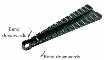
However, for anyone doing a lot of construction or anyone wanting to get a very professional look, then it is possible to use a bending former like the one shown below.
These items are typically a small plastic element with slots for the body of the resistor and the leads. The resistor can be placed within the bender and the leads bent over the sides.
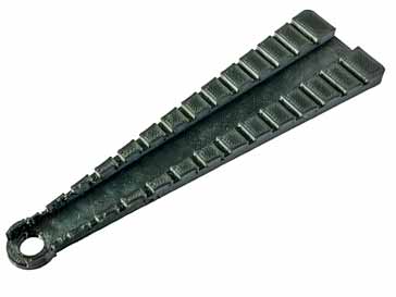
There are different slots for different sized resistors and PCB hole spacings, so it is necessary to select the right spacing for the particular board being used.
These lead bending formers are available, normally very cheaply from a number of outlets as well as the major electronic component distributors.
It should also be remembered that on occasions the hole spacing for resistors and some capacitors, etc is such that they may need to be stood on end, i.e. vertically mounted, and the lead bent round and back down so that the much smaller hole spacing can be accommodated.
Standing components up from the board
On some occasions it may be necessary to stand a component up from the board. This may be done to reduce the effects of the high temperatures from soldering, or the prevent the effects of any bending or flexing of the board as can sometimes happen.
Ceramic capacitors in particular can be prone to damage in this way, and if they are not stood up from the board, the lead lengths will be so short that heat and any board flex can cause damage - ceramic capacitors can crack under bending conditions, so care must be taken if the leads can be very short.
To overcome this a rounded curve of "C" shape can be bent into the component leads so that they stand up from the board.
Great care must be taken when doing this, as it is easy to damage the component by placing it under too much strain.
If there are many component for which this needs to be done, then special tools can be bought, but they tend to be a bit more specialist and rather expensive.
Bending transistor leads
Although it is perfectly permissible to bend the round wire leads for small transistors transistors, care must be taken not to bend them at the junction with the package. This can cause a very sharp bend that could cause the wire to break.
Instead bend them a little distance from the package so that the wire bend can be less sharply.
It is also possible to use special stand-off spacers for the TO18 packages. Although these are an additional item to think of, they can make the job of spacing the leads tot he transistor much easier.

Issues can arise if the leads for the TO220 style packages are bent outwards. If this is done then there is a risk of damaging the package and hence the semiconductor device inside.
whilst it is possible to bend the leads backwards and forwards, care must still be taken when bending or forming these leads to ensure that they do not break or damage the package.
Bending IC leads
IS leads should rarely need bending or preforming. They come preformed to the standards that are required for printed circuit boards and also for the IC holders that are sometimes used.
Occasionally it may be found that the dual in line or DIL ICs have the ends of the leads a little far apart. A little gently persuasion of the leads, possibly by pressing all the leads on one side of the IC together to squeeze them in slightly might be needed.
Otherwise it is best to leave IC leads alone as much as possible.
The leads for some of the large quad flat pack ICs used in surface mount boards should never be touched. Get these out of line and it is virtually impossible to get them back in line again.
Also with many of these ICs being very sensitive to static, they should not be touched and any work with them left tot he automated processes normally used.
Pre-forming axial component leads so that they can fit a project, printed circuit board or whatever can be achieved in a very professional manner with a few tools.
However, when undertaking this care should be taken not to damage the components, especially cracking them by applying too much force close to the package. Treat all components with care
More Construction Ideas & Concepts:
Soldering
SMT component soldering
ESD - Electro-Static Discharge
PCB manufacture
PCB assembly
Return to Constructional Techniques menu . . .

