LED Chip-on-Board, COB: A Comprehensive Guide
Understand the features & benefits of LED COB, Chip-On-Board technology for electronics: higher light levels & from smaller area, improved reliability, etc.
Home » Electronic components » this page
Light Emitting Diode Tutorial Includes:
Light emitting diode
How does a LED work
How a LED is made
LED datasheet specifications
LED lifetime
LED packages
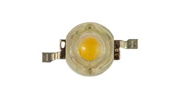
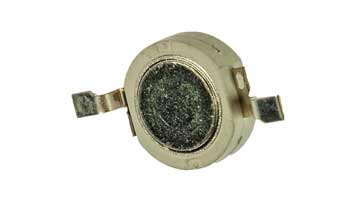
High power / brightness LEDs
LED lighting technology
LED COBs
Organic LEDs, OLEDs
Other diodes: Diode types
LED Chip-On-Board or COB assemblies are being used increasingly to enable a large number of individual light emitting diodes to be mounted within a single assembly or module.
These COB LED modules provide many advantages and as a result they are being using increasingly in a growing number of lighting circuit designs and products.
With the advantages they provide, LED Chip-On-Board, COB modules are displacing modules made from matrices of either surface mount LEDs or leaded ones.
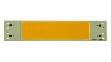
COB LED modules and assemblies can be obtained in a huge variety of formats from traditional modules of varying sizes, shapes, wattages, voltages to tapes which can be used for all sorts of strip lighting. Again, these are available in a huge number of variations.
Advantages of LED COB modules
LED COBs have many advantages over using a matrix of discrete LEDs, either leaded or SMD LEDs.
As a result of their advantages, it means that the COB approach is very much better and as a result, they are the only viable option for many lighting style applications and electronic circuit designs.
High light output for area taken: This is achieved because a COB is able to contain many more individual LED elements compared to more traditional construction techniques using leaded or even SMD LEDs. A figure of up to fifty times is sometimes quoted, although for smaller arrays the figure is likely to be much less.
Cost savings: Because the module comes ready formed, there are significant cost savings for using COBs because each individual LED element is already contained in the single module and the individual LEDs do not need to be incorporated individually into the module.
Even light over surface area: Because of the small spacing and the construction of the dome or cover over the module, a LED COB is able to produce a very even level of light all over the emitting surface area of the module. Light is emitted evenly over the surface of the light panel. This can be a significant benefit to applications where lighting levels close to the source need to be even, as in some photography applications.
Reliability: As all the LEDs are bonded onto a substrate, this makes the whole module very reliable - far more reliable that discrete LEDs mounted on a PCB. This is mainly dues to the fact that soldering of the individual SMD LED chips or leaded components is not necessary as each chip is directly mounted onto the substrate. This means that there is a smaller number of electrical joints and this results in a much lower failure rate.
Design simplicity: The LED COB incorporates all the wiring for the LEDs and only tow connections are required for the COB. This considerably simplifies the printed circuit board or other assembly within an overall unit. This makes COBs far easier to incorporate into an electronic circuit design than an array of discrete leaded or SMD LEDs.
Thermal performance: COB LEDs are able to offer much better thermal performance, with heat removal being far easier to implement. This results in better performance and increased reliability.
COB LED lighting applications
There is an enormous range of areas where COB LEDs can be used, and this is growing as the costs fall, the range of available devices increases and their performance improves.
These LEDs are generally used for various forms of lighting - solid state lighting, SSL. They are being used in various forms of general domestic and industrial lighting. With the light coming from an area rater than distinct points, it is more pleasing.
These COB LEDs can be used in portable lighting: torches etc where the performance and improved light output per unit area gives them an edge over more traditional LED based torches and other devices.
They can also be used in down-lighters, where the dispersed lighting gives them a great advantage over a series of LEDs in an assembly or string of lights. COB LED strips are becoming more popular and widely available. These COB LED strips are easy to use and give excellent performance.
They also have applications in photography where the uniform light can be ideal for backlighting, etc. That said, care must be taken with the spectral purity.
There are obviously very many more areas where COB LEDs can be used, and with time, this will only increase.
COB LED specifications
As with any other electronic component, LED COB performance is specified in the data-sheets issued by their manufacturers.
A variety of different parameters are specified, and some of the major ones are highlighted in the list below.
Colour temperature: This is a photographic or lighting term that is applied to the array and it refers to the warmness of the light - assuming it is a white light. Warm colours have more off a reddish glow to them and make them feel warmer, whereas cool whites have more blue in them.
The temperature is often quoted in terms of the light being warm, very warm or standard / daylight. It may also be quoted in terms of a colour temperature on °K. Colour temperature generally ranges from 2700-3300°K for a warm light to 3300-5300°K for a cool light. Standard daylight on an overcast day is taken to be 6500°K.
Forward voltage: This is the voltage across the module, typically when operating at the recommended current. A variety of operating voltages are often available, and the required one can be selected for the particular electronic circuit design in question. The voltage will be stated for that given current level.
Maximum forward current: This is the maximum forward current that the COB can withstand. The device should not be operated at this point of beyond. As with any electronic component it is always advisable to operate the COB within its specifications so that the component is not stressed and the reliability is maximised.
Luminous Flux: This is a measure of the light emitted from the COB at a given forward current and operating temperature.
Relative Spectral Distribution: This is a measure of the wavelengths where the most emitted light is concentrated. Although the colour temperature is important, the light should contain a mix of all wavelengths to give a good simulation of natural light. Electronically created light does not emit all wavelengths equally. This may not be an issue for most applications, but where colour is important, this specification or parameter needs to be investigated.
Temperature: All electronic components are affected by temperature. So too are LED COBs. This specification defines how the maximum current rating changes with the temperature of the COB.
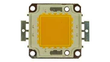
What exactly is a LED COB
A LED COB is essential a module where multiple LED chips - possibly the minimum matrix practicable number is 3 x 3 or 9 LEDs, but normally much larger matrixes are used.
The individual LED chip is a bare die, in other words it does not have its own lead-frame - this means that it is the basic semiconductor LED without any connections, packaging, etc around it. This means that it is small while still being able to produce a good level of light output.
Within the COB LED module, the individual LED chips are bonded directly to a substrate by the manufacturer making the module robust and reliable.
The substrate is thermally very efficient, and with the individual LED chips bonded to it, this gives a very effective way for heat to be removed. This means that the heat removal from the individual LEDs is far more effective and this enables the density of LED chips to be increased while still running them at a low level.
The fact that bare LED chips are used also means that very high packing densities can be achieved as the individual chips can be mounted very close together and this enables high intensity levels or light density levels to be emitted from a smaller area than is possible with single packaged LEDs, either particularly leaded but also SMD LEDs.
Once the substrate is complete, the lead-frame is added and also the COB manufacturer applies a uniform phosphor coating to the entire array of chips. As the LED chips emit a blueish light, the phosphor coating enables the final output to become the required white colour temperature. White, warm white and very warm white are descriptions that are often used.
COB LED circuit design guide
Although COB LEDs may appear to be different to standard LEDs, they are essentially just a matrix of LEDs and as such they have the same characteristics but with different voltage levels and current levels.
When undertaking an electronic circuit design using it is necessary to drive the LED array in the way that provides the optimum performance fort he given situation.
Although it is possible to use discrete circuits, it is also possible to use LED drivers. These come as either integrated circuit chips for incorporation into a particular electronic circuit design, or as complete drivers that take power from the mains or power line input and then drive the COB LED module directly.
As the COB LEDs only operate on DC with the specified voltage and current, the complete LED driver modules convert the incoming AC line input power to the required DC voltage with the current capability required.
It is obviously necessary to ensure that the LED driver module can fully supply the power required and in the way that it is needed. These COB LED driver modules are often used as external units to power a COB LED or series of COB LEDs.
There are two types of LED driver circuit:
• Constant Current
Constant current drivers of supplies are the more intuitive method for powering LED systems. As the correct level of current can be provided, this prevents the LEDs from being over driven.
Typically constant current drivers are used for series connected COB LEDs or single devices.
• Constant Voltage
Although standard LEDs tend to be driven my a constant current or current limited source, COB LEDs may often use a constant voltage form of driver or supply.
Constant voltage drivers used for these LEDs maintain a steady output voltage - effectively they are a voltage regulated supply. They maintain their output voltage steady and vary their current output.
Constant voltage drivers or supplies are often used in parallel wired systems because in this way the current level of current can more easily be provided for each of the parallel arms.
When using a constant voltage driver, the correct voltage must be set very carefully to ensure that the LEDs do not draw too much current resulting in damage.
It can be quite difficult because the IV characteristics of the LEDs change with temerpature.
Heat-sinks for COB LEDs
COB LEDs are able to produce a large amount of light from a very small area, and this means that, even though they are very efficient, heat will still be dissipated, especially for the high power ones that are becoming available now. This heat needs to be removed otherwise the COB LED will overheat and it could be destroyed.
In order to remove the heat from the COB LED, most of them have a flat metal surface on the back which is designed to transfer the heat from the LED itself to a heatsink of some form.
There are two main forms of heatsink that are available and can be used:
Passive heatsink: These heatsinks are the type that are physically in contact with the base of the COB LED which has a metal back. The heat is then transferred to the heatsink which is typically a metal, normally aluminium, item. This often has fins to be able to dissipate the heat it accepts into the air.
Where much smaller levels of heat are to be dissipated, the COB LED may be mounted on a PCB, and the PCB copper can be used to remove heat. Obviously the copper must be on the surface of the PCB to make direct contact with the LED, and the area of copper is normally relatively large so the heat can be transferred to the air.
Active heatsink: Another form of heatsink is known as an active heatsink. This involves a fan or other active method for removing heat from the area of the LED, or other device for that matter. Often a passive heatsink is used as the primary means of removing heat, and then the fan blows air or other coolant over this heatsink.
Using an active heatsink means that a smaller heatsink can be used, although the fam will add to its size, it will require powering, and it will also have some noise associated with it.
One of the issues with active heatsinks is that it relies on the fan running, and if this should stop for any reason, the COB LED will overheat and damage is likely to result.
When using heatsinks of whatever type, active or passive, it is wise to calculate whether the heatsink type selected can dissipate sufficient heat in the temperature environment it is in to keep the COB LED sufficiently cool.
COB LEDs, Chip-On-Board LEDs are now well established although in comparison to traditional LEDs they may be considered a newcomer to the market. These COB LEDs are widely available and for the performance they provide, they can be obtained very cheaply making them an ideal choice for many electrical and electronic circuit designs. They can also be obtained in a variety of formats: square matrixes of various sizes, rectangular modules and in a strip formation. This means that there will almost certainly be a suitable COB LED module for any particular situation.
More Electronic Components:
Batteries
Capacitors
Connectors
Diodes
FET
Inductors
Memory types
Phototransistor
Quartz crystals
Relays
Resistors
RF connectors
Switches
Surface mount technology
Thyristor
Transformers
Transistor
Unijunction
Valves / Tubes
Return to Components menu . . .