Voltage is one of the easiest and most common measurements to make using an analogue multimeter or a digital multimeter, DMM.
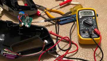
Voltage measurements also have the advantage that they can be made directly on the circuit in question. Unlike current measurements it is not necessary to pace the meter into the circuit - instead the voltage measurements can be made by probing directly onto the relevant points of the circuit.
Voltage measurements are easy to make with both analogue and digital meters and in essence the way the measurements are made is the same - the only difference is that one meter is analogue and the other is digital. There are no different techniques to be used as in the case of making resistance measurements.
How to make a voltage measurement - the basics
Voltage measurements look at the potential difference between two points. In other words they look at the difference in electric pressure at the two points. In most cases the voltage is measured between a particular point and the ground or zero volt line on a circuit. However this does not mean that the voltage cannot be measured between any two points.
Voltages are measured simply by placing the digital multimeter across the two points where the voltage is to be measured.
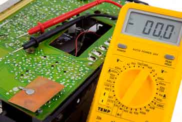
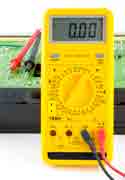
How to make a voltage measurement -with a digital multimeter, DMM
Digital multimeters are particularly easy to use to make voltage measurements which they can do with great accuracy.
... it is very easy to measure voltage with a digital multimeter, DMM ....
If there are different sockets on the DMM for different ranges, e.g. current, resistance, etc, insert the probes into the correct sockets on the meter. Usually a meter will be provided with two leads, one black, and the other red. The black one is normally taken as the negative one. This one is connected to the negative or "common" socket on the meter. The red one is connected to the positive socket.
Turn the meter on
Set the meter range to accommodate the largest expected value - note: some DMMs will be auto ranging and it is only necessary to select the voltage capability. Note that DMMS are normally able to operate with both negative and positive values on the probing or red lead.
First probe the low voltage point - often this may be ground and there may even be an alligator / crocodile clip on the black or ground probe that can be connected to a suitable ground point. This saves trying to probe two points at once.
Probe the higher voltage point with the probe on the red lead.
If necessary, adjust the range switch to obtain the best reading.
Note the reading
Either make the next reading or if finished remove the probes and turn the meter off.
It is always best to return the meter range switch to the highest voltage range available as this could save damage of the meter is used before the proper range is set.
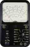
How to make a voltage measurement with an analogue multimeter
Analogue multimeters are also very easy to use, but may need to be handled with a little more care to prevent damage - they do not have all the protection of a digital multimeter.
... analogue multimeters are also able to measure voltage very easily ....
On many analogue multimeters there are different sockets for voltage / hesitance and current. Inset the meter end of the probes into the required sockets Usually a meter will be provided with two leads, one black, and the other red. The black one is normally taken as the negative one. This one is connected to the negative or "common" socket on the meter. The red one is connected to the positive socket. It is important to ensure that the negative lead is in the negative or common connection.
Set the meter range to accommodate the largest expected value and allow a little extra as damage could result from high voltages or voltage reversal.
Try to ensure that the positive voltage is applied to the positive lead (as best as possible without actually probing).
First probe the low voltage point - often this may be ground and there may even be an alligator / crocodile clip on the black or ground probe that can be connected to a suitable ground point. This saves trying to probe two points at once.
Probe the higher voltage point with the probe on the red lead.
Check that a positive deflection of the meter is obtained. Then adjust the multiuser range switch to reduce the value of the range. This is done until the largest deflection is seen on the meter without it going over the top of the range. In this way the most accurate reading is obtained.
Note the reading
Either make the next reading or if finished remove the probes.
It is always best to return the meter range switch to the highest voltage range available as this could save damage of the meter is used before the proper range is set.
Tips for making voltage measurements
Although voltage measurements are easy to make , a few simple tips can make the measurements easier to make and also more accurate.
Connect meter earth connection to ground: It is often difficult to hold two probes, steady a board and then adjust a switch in the meter all at the same time. There is also the risk of the probe slipping. To ease matters, many multimeters have a crocodile / alligator clip. A crocodile / alligator clip can be used to make the ground connection when measuring voltage with a multimeter
This can be clipped onto a suitable earth point, and then all the measurements made relative to ground . . which what is normally required. Where the voltage between two different points is needed, then each point can be measured and the difference between them taken.
After use return to highest voltage range: On meters were the ranges are switchable, it is always best to return the switch both e highest AC voltage range. In this way, if the meter is hooked up before the range switch is set, then no damage can result. This is a good habit to develop.
Voltage measurements are very easy to make using either a digital multimeter, DMM or an analogue multimeter. These measurements are probably the most common measurements to make with a multimeter.
Knowing how to make a voltage measurement with a multimeter is a particularly useful skill and one which will be used time and again.
Fact of the day: It was on 26 Apr 1900 that Charles Richter was born. He was the seismologist who was the inventor of the Richter Scale that measures earthquake intensity.
Quote:Education is the most powerful weapon you can use to change the world. Nelson Mandela
Point to ponder: The degree of technical competence is inversely proportional to the level of management.